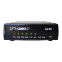
Installation
11 User’s Manual - SM202T/SMV23 Modem
NOTE:
It is important to follow the steps below to configure the modem’s DIP
switches to match your DTE/RTU interface requirement and the transmission
line characteristics. If you are not certain about your system’s parameters or
the leased-line configuration, please contact your network administrator for
assistance.
1. Configure the modem using the DIP switches and jumpers. See pages 13 .
2. Connect to a transmission line. See page 18.
3. Connect to a voltage source. See page 19.
4. Connect a DTE device. See page 20.
Configuring the Modem
You configure the modem using the 8-position DIP switch and two sets of configuration
jumpers on the printed circuit board of the modem labeled S1, JP1 and JP2.
Configuration DIP switches S1 for the stand-alone and rack-mount modems are identical.
Their descriptions in this user’s manual apply to both modem versions. Configuration jumper
JP1 for the standalone and rack-mount modem card is used to select transmit output level.
It is important to follow the steps described below, in the order shown, to ensure that you
configure your modem properly using the modem DIP switches:
1. Use DIP switch 1 (S1) to configure the modem for your host DTE interface and
network topology. Using S1, you select the modem’s serial port to match your
host computer or RTU devices, and other DTE specific operating parameters.
2. Use Jumper (JP1) to select the modem’s transmitter output level to match your
specific leased line conditions. The JP2 is used only in the standalone modem for
selecting either RS-232 or RS-485 interface.
3. After you change the DIP switch settings, recycle power to the modem to have
the settings take effect.
NOTE:
The DIP switch settings will not take effect until you recycle power to the
modem.
To access the configuration DIP switches and jumpers on the stand-alone modem:
1. Ground yourself to discharge any ESD, which might cause damage to the
sensitive devices on the modem board.
2. Use a small Philips screw driver to remove the two screws at the bottom of the
enclosure and remove the top cover. The location of the DIP switches and
jumpers for the stand-alone modem are shown in Figure 2-4. For DIP switches
and jumpers on the rack-mount plug-in module, see Figure 2-5.