Installation
20 User’s Manual - SM202T/SMV23 Modem
Connecting to an RS-232 Device
The modem back panel provides a female, 9-pin RS-232 connector that accepts an attached
RS-232 device (see Figure 2-2 on page 10). This connector accepts a standard connection
to a DTE (RTU) that conforms to the pin assignments shown under “RS-232 (DTE)
Interface” on page 26.
Connecting to an RS-485 Device
The modem rear panel provide an RJ-11C module jack connector for a 4-pin RS-485 or RS-
422 interface in the event that your DTE or RTU does not support the RS-232 interface (see
Figure 2-2 on page 10 and Figure 2-6).
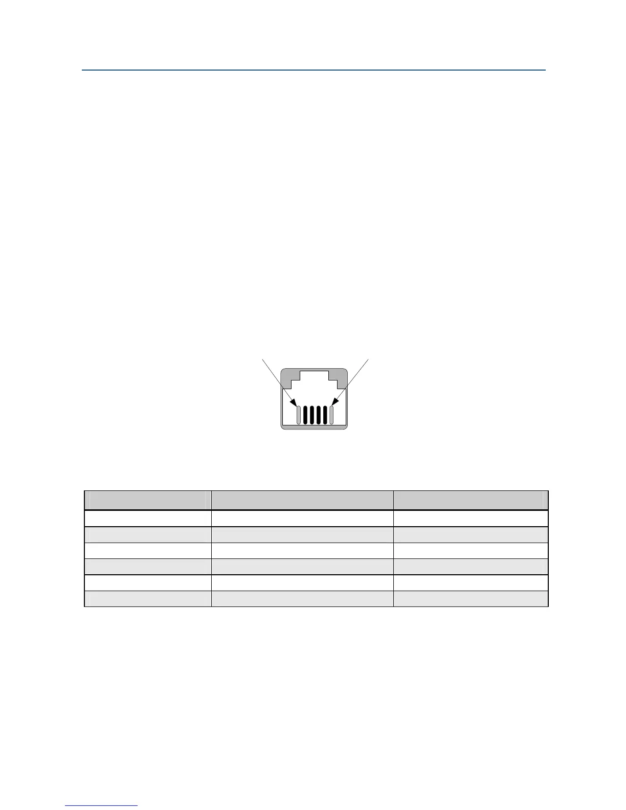
The pin assignments for the RS-485 interface are listed in Table 2-3.
Pin #6 Pin #1
Figure 2-6. Pin Locations on the Modem’s RJ-11C Jack
Table 2-3. RJ-11C Modular Jack Pin Assignments
RJ-11 Pin Number… Corresponds to Signal Name Modem Input or Output
1 Not Used NA
2 RxD+ Output
3 RxD- Output
4 TxD+ Input
5 TxD- Input
6 Not Used NA