Installation
18 User’s Manual - SM202T/SMV23 Modem
Connecting to a Transmission Line
The modem has a transmission line interface (RS-11C) that can be configured for 2- or 4-
wire analog connection, where in 4- wire connection, one pair (Tx-A and Tx-B) is used to
transmit data and the other pair (Rx-A and Rx-B) is used to receive data. The transmit pair
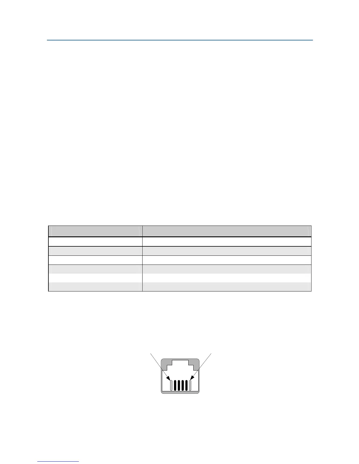
and receive pair are non-polarized. Table 2-44 shows the pin numbers and corresponding
signals for the modem. Error! Reference source not found. shows the transmission line
interface.
NOTE:
For communication to occur, the Rx line of one modem must connect to the Tx
line of the other modem. The modem’s Tx/Rx pair are non-polarized.
NOTE:
The modem does not support leased-line operation with DC shielding current.
Leased-line connector pin assignments for the rack-mount module can be
found in the documentation for your Motorola/UDS RM16M.
Table 2-4. Transmission Line Connector Pin Assignments
This Pin Number… Corresponds to This Signal…
1 Not Uesd
2
Rx
3
Tx (Tx/Rx)
4
Tx (Tx/Rx)
5
Rx
6 Not Used
NOTE:
When 2-wire half duplex is used, the center pair must be used for both
transmit and receive.
Pin #6 Pin #1