DM4380 – Installation Guide
204.4336.00 - October/2019
Power Supply cooling inlets
Auxiliary Safety Grounding
Equipment cooling outlets
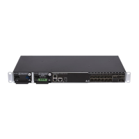
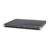
Table 1 – DM4380 12XS+3CX Interface Description
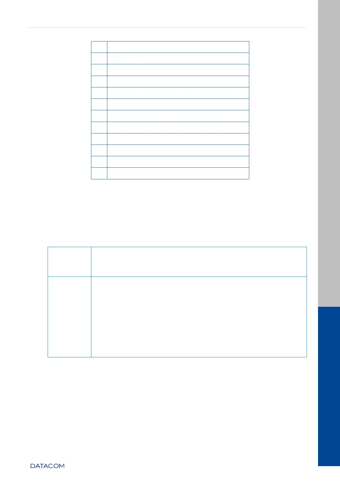
3.3 EQUIPMENT STATUS LEDS
The DM4380 Switch has two statuses indicating LEDs in the front panel, the LED
ALARM/FAIL located in the Mainboard and the LED PWR located in each PSU. The table
below describes the behavior of the status LEDs of the equipment.
ON GREEN: Indicates that the power supply is running and that
the equipment is powered or on standby ready to take over the
load.
OFF: Power supply with problems or not powered.
OFF: Equipment operating normally, without detected failures
or alarms.
ON RED: Indicates that the equipment is in a state of internal
failure.
ON BLINKING RED (slow): Indicates that the equipment is in a
lower gravity alarm state.
ON BLINKING RED (fast): Indicates that the equipment is in a
lower gravity alarm state.
When the power is connected to the equipment, this LED will turn
red for a short time, and then will turn off.
Table 2 - Status LED behavior
3.4 SERIAL CONSOLE INTERFACE (RS-232)
The DM4380 equipment line has a console port for local management. The console port
uses an RJ45 connector. A cable with a male RJ45 connector and a female DB9
connector must be used for the connection to a computer or laptop.
The serial console cable is an accessory included in the DM4380. Additional cables can
be purchased separately via code 710.0137.xx or assembled as described in the