Product Manual - DM991 Series V Family - 204.4092.08 13
• Both TX pind are used for port A in the DSL interface. Both RX pins are used for port B in
the DSL interface (for model 4W only). More details are provided in the Table 5.
• Dial Backup pins are used for the E1 interface. Pins A and B are for interface input (IN)
and pins C and D are for interface output (OUT). More details are provided in the Table
12.
2.2. DM991C/CE 2W/4W
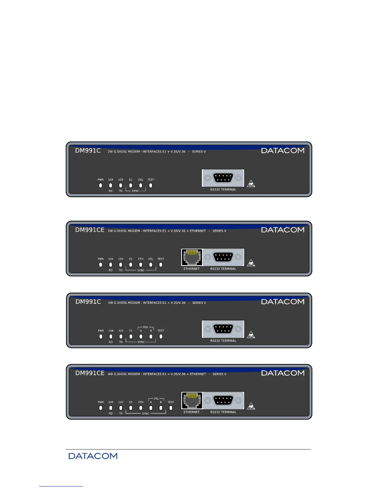
2.2.1. Front Panel
The Figure 6 represents the DM991C 2W modem panel, Figure 7 represents the DM991CE 2W modem
panel, Figure 8 presents the DM991C 4W modem and the Figure 9 presents the DM991CE 4W modem
Figure 6. DM991C 2W Front Panel
Figure 7. DM991CE 2W Front Panel
Figure 8. DM991C 4W Front Panel
Figure 9. DM991CE 4W Front Panel