EasyManua.ls Logo

Datacom DM991CE - Dips Summary

Default Icon
89 pages
Print Icon
To Next Page IconTo Next Page
To Previous Page IconTo Previous Page
Loading...
Product Manual - DM991 Series V Family - 204.4092.08 36
8.12. DIPs Summary
DIP Function OPERATION POSITION
A1 to A5 Speed selection
Table See table
Internal
OFF / ON
External
ON / OFF *
Regenerated
OFF / OFF
External RX
ON / ON
Accepts
ON
Does not
accept
OFF*
Enabled
ON
Disabled
OFF*
Enabled
ON
Disabled
OFF*
Enabled
ON
DIsabled
OFF*
V.35
ON*
G.703
OFF
LTU
ON*
NTU
OFF
Management
ON
Dip-Switches
OFF*
Enabled
ON*
disabled
OFF
Enabled
ON
disabled
OFF*
Enabled
ON*
disabled
OFF
B8
4W Operation
Converter Mode
#
B5 Terminal type
B6 Configuration
B7
Ethernet
B3
<<
CRC4
B4
Interface
B1
<<
Cross-Connect CAS
B1
<<
Timeslot 16
A6/A7 Transmissio clock
A8 LDR request
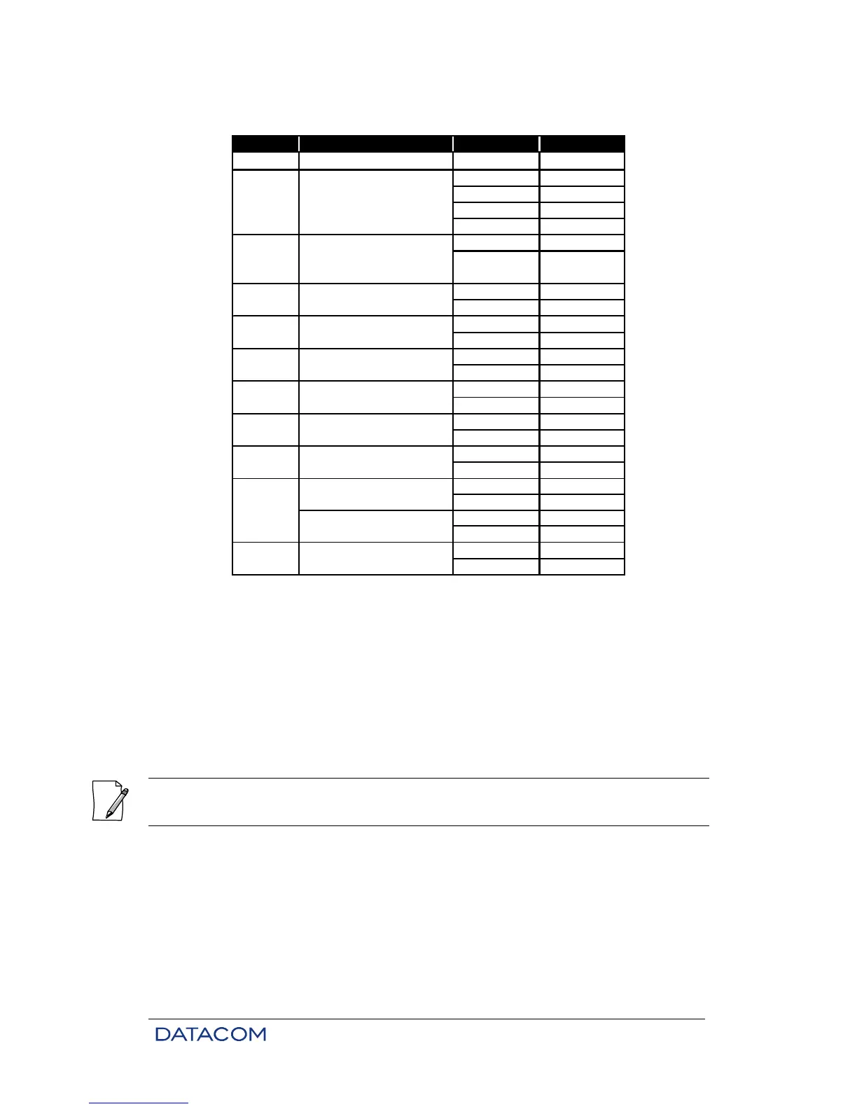
Table 18. DM991S/SE – DIPs Summary
See Table 16.
* Factory standard position
† This DIP loses purpose when DIP B7 is se to ON.
Only for DM991SE model.
# Only for DM991S model
Only for modems that works on four wires (4W).
<<These DIPs have no function when DIP B4 is ON and DIP B7 is OFF.
The DM991SE modems leave factory configured to internal transmission clock (A6=OFF/A7=ON)

Table of Contents

Related product manuals