Chapter 1. Introduction
Table 1-1. System LEDs
LED CONDITION STATUS
Power ON System is powered on
OFF System is powered off
Fail ON Indicates hardware failure
OFF System is operating normally
Stack * Blinking Switch is operating in stack mode (master)
ON Switch is operating in stack mode (slave)
OFF Switch is operating in standalone mode
Sys** ON System is booting
OFF System is ready
Alarm ON System Alarm is active
OFF System Alarm is inactive
• * valid only for DmSwitch 3000 family.
• ** valid only for DmSwitch 2000 family.
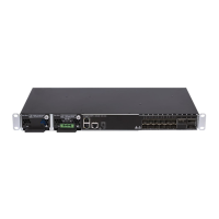
1.2.3. Port Leds
Port LEDs indicate data activity and speed on each port. Their location is shown in the next Figure and
their status on the table below.
Figure 1-10. Port LEDs Location
5