Chapter 1. Introduction
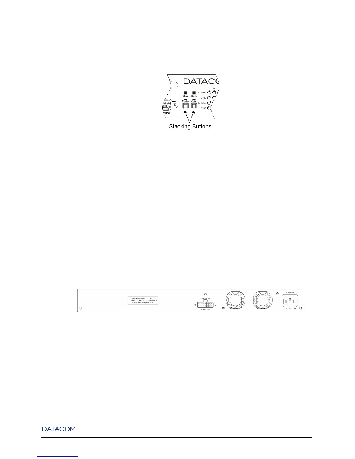
one switch in the stack to operate as the master. The entire stack will be managed by this unit.
Figure 1-12. Stacking Buttons Location
1.3. Rear Panel Description
The Rear Panel is described separately for the F1, F2/G1 and F3 versions.
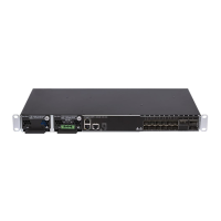
1.3.1. DmSwitch F1 Rear Panel
The DmSwitch F1 Rear Panel contains one AC power connector and one Redundant Power Unit (RPU)
outlet.
Figure 1-13. DmSwitch F1 Rear Panel
The AC power input accepts any suply voltage in the range from 100~240 VAC at 50~60 Hz. An optional
external 12VDC RPU can be used by connecting it to the RPU outlet.
8