Chapter 1. Introduction
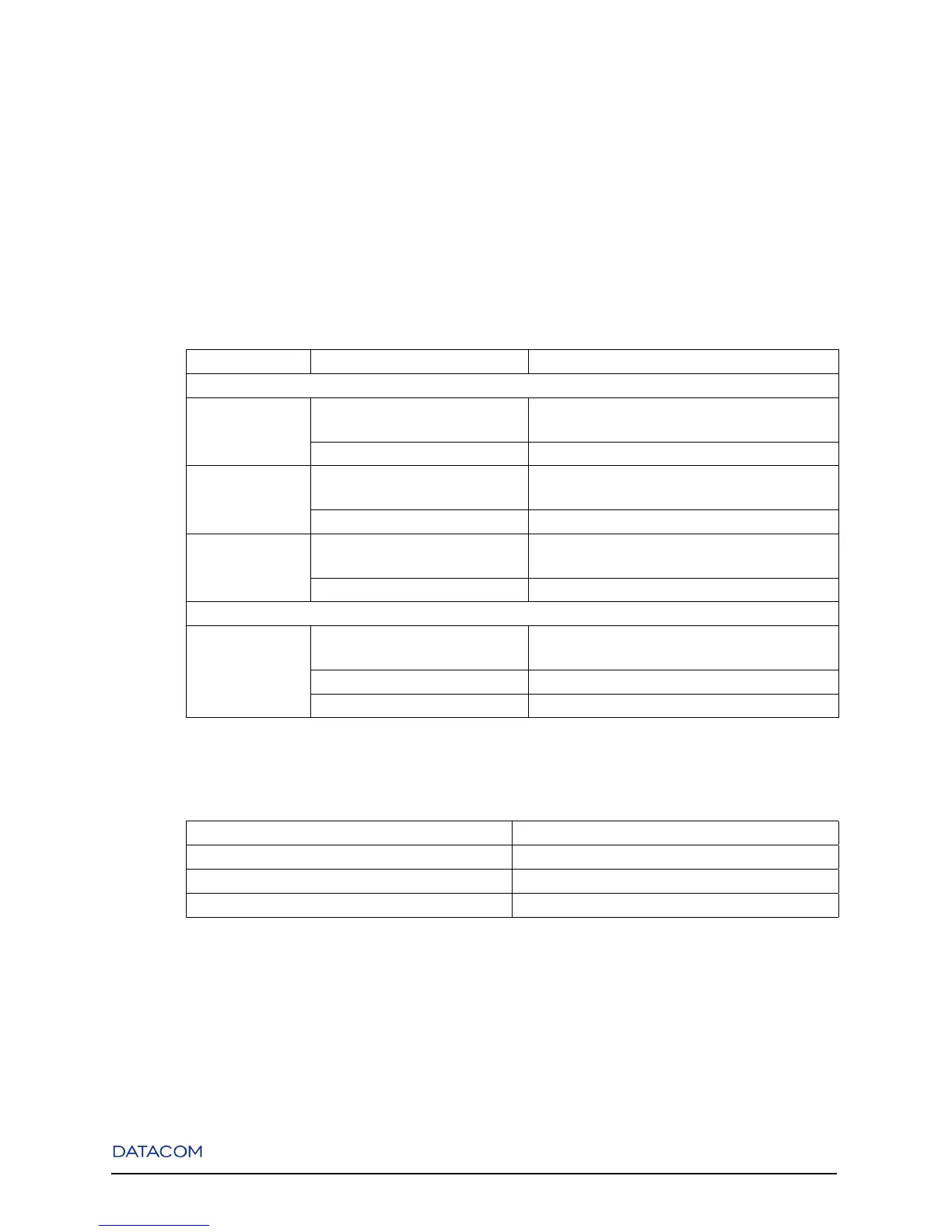
The Alarm port contains 3 alarm inputs and 1 alarm output. The inputs accept voltage differences from
8V to 60V (indicating alarm on) or less than 8V (indicating alarm off).
The Alarm output works as follows. In an alarm situation or when the device is powered off, pin 4 (com-
mon) is short-circuited with pin 9 (NF). When alarm is off, the pin 4 turns to a short circuit with pin 5
(NA), while pin 9 keeps isolated.
Alarm pin assignments are provided in the following table:
Table 1-3. Alarm Port Pins Assignments
Input/Output Pin Name DB9 Pin Number
Alarm Inputs
Alarm Input #1 Common 6
Input 1
Alarm Input #2 Common 7
Input 2
Alarm Input #3 Common 8
Input 3
Alarm Output
Alarm Output #1 Common 4
NA 5
NF 9
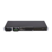
Next table shows the Console Port pin assignments:
Table 1-4. Console Port Pins Assignments
Serial Port Pin Name Pin Number
RX 3
TX 2
GND 4 and 5
1.2.5. Slave/Master and Stack/Uplink Buttons
The DmSwitch 3000 family contains two buttons to control stacking. When pressed, the Stack/Uplink
button makes the Switch operate in standalone mode, allowing the ports 27 and 28 to be used as normal
Ethernet ports instead of stacking ports. When stacking mode is selected, the Slave/Master button selects
7