Chapter 3. Switch Installation
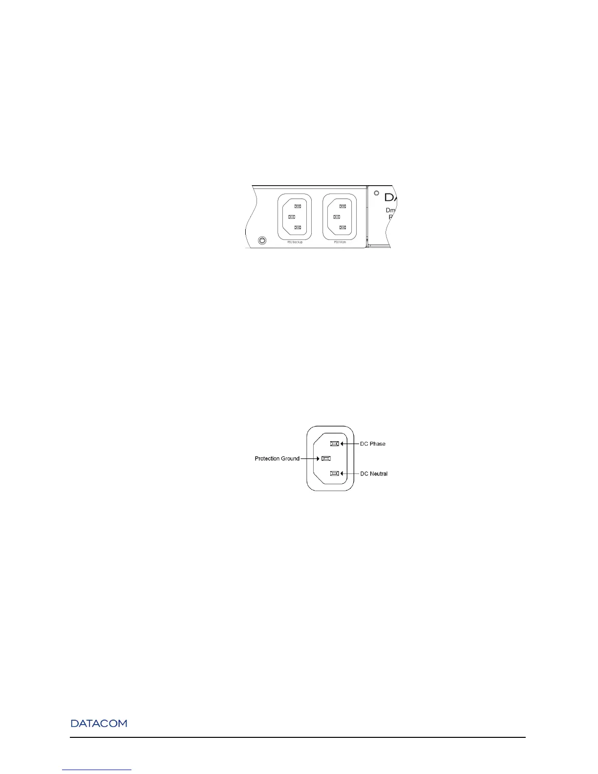
The DmSwitch 2000 G1, 3000 F2 and 3000 F3 have two AC/DC power connectors at the rear panel, one
for each power source. If you are using both redundant power units, use two power cables to connect
them.
Figure 3-3. DmSwitch F2 Power Connectors
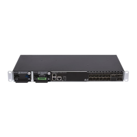
If DC power is used, the power cable should be cut close to the AC sockets connection plug and connected
in a way that the socket central pin corresponds to ground protection and the other 2 pins supply the power,
as seen in the next Figure. The equipment shelf is connected directly to protection ground.
Figure 3-4. AC/DC Power Suply Connector
3.6. Installing/Removing a G1/F2/F3 version Hot-Swap
Power Unit
The DmSwitch G1/F2/F3 versions are able to work with one or two Hot-Swap Power Units. Follow the
next instructions to install or remove a Power Unit:
17