Chapter 1. Introduction
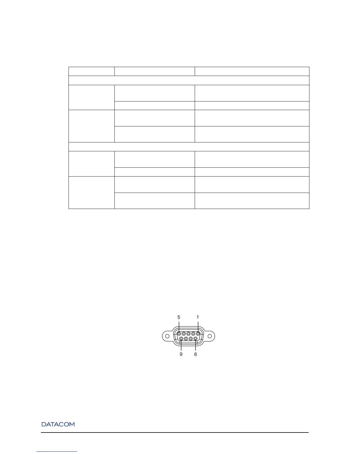
Table 1-2. Port LEDs
LED CONDITION SYSTEM STATUS
Ports 1 to 24 (DmSwitch 3000) / 1 to 4 (DmSwitch 2000) - Fast Ethernet
Link/Act ON/Blinking Connection established. Blinking indicates port
activity.
OFF No connection established.
10/100 (F1/F2),
Speed (G1/F3)
ON Indicates that a 10Mbps connection was
established (when Link/Act is ON/Blinking).
OFF Indicates that a 100Mbps connection was
established.
Ports 25 to 28 (DmSwitch 3000) / 5 to 8 (DmSwitch 2000) - Gigabit Ethernet
Link/Act ON/Blinking Connection established. Blinking indicates port
activity.
OFF No connection established.
10/100/1000
(F1/F2), Speed
(G1/F3)
ON indicates that a 10/100Mbps connection was
established (when Link/Act is ON/Blinking).
OFF Indicates that a 1000Mbps connection was
established.
1.2.4. Console and Alarm Ports
The DmSwitch 2000G1 and the DmSwitch 3000F1 contain one DB9 Console connector on their front
panel. The DmSwitch 3000F2 and DmSwitch 3000F3 contain two DB9 connectors on their front panel.
The upper connector is the Alarm port and the lower is the Console port.
The pin-out of both console and alarm ports are shown in the next figure.
Figure 1-11. Console and Alarm Port Pins Order
6