3. MECHANICAL MOUNTING
The emitter and receiver units have to be mounted with the relevant sensitive
surfaces facing each other. The connectors must be positioned on the same
side and with the operating distance of the model used (see section 10
“Technical data”).
The two units must be aligned and parallel as much as possible.
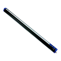
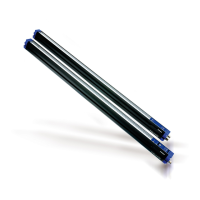
To mount the device, insert the threaded pins supplied (see Fig.3) in the slots
present on the two units.
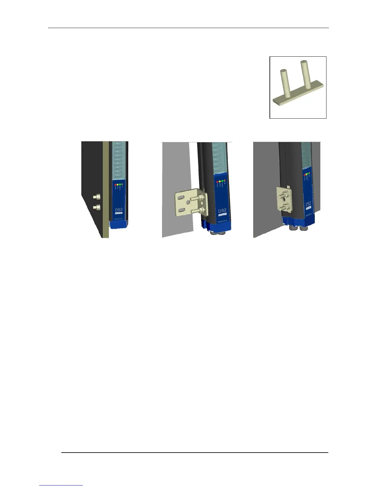
Depending on the particular application and/or type of support, the operator
can use the fixing pins or the rigid fixing brackets supplied to mount the two
units (see Fig.4).
Fig. 4
Rigid fixing brackets can be used where no big mechanical corrections are required during the
alignment operation.
Rotating supports for the correction of the unit inclination of ±1° on the medial transversal axis and of
±5° on the longitudinal axis, are available on request.
In applications with particularly strong vibrations, the use of anti-vibration shock absorbers able to
reduce the impact of vibrations together with threaded pins, rigid brackets and/or rotating supports are
recommended.