DS6300 PROFIBUS
8
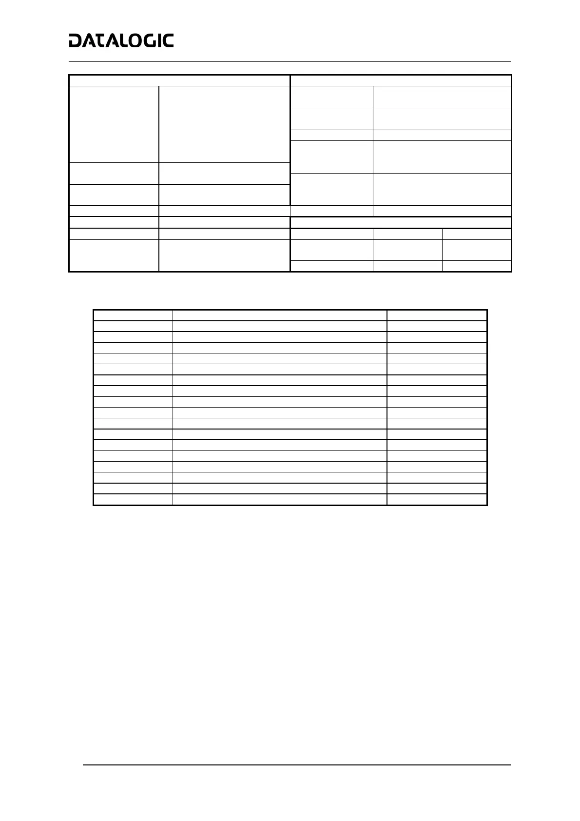
SOFTWARE FEATURES ENVIRONMENTAL FEATURES
Interleaved 2/5
Readable Codes
Code 39 standard
Operating
Temperature
0° to +40 °C (+32 to +104 °F)
Codabar
Code 128
Storage
Temperature
-20° to +70 °C (-4° to +158 °F)
EAN 128
Humidity
90% non condensing
Code 93 (standard & full ASCII)
EAN/UPC
Vibration
Resistance
IEC 68-2-6 test FC
1.5 mm; 10 to 55 Hz
Code Selection
Up to 10 codes during one
2 hours on each axis
reading phase
Shock Resistance
IEC 68-2-27 test EA
Headers and
Up to 128-byte headers and 30 G; 11 ms
Terminators
128-byte terminators
3 shocks on each axis
Protection Class
IP50
Operating Modes
On Line, Automatic, Test,
PHYSICAL FEATURES
Config. Mode
Genius™ utility program
Std Models Oscill. Mirror
Dimensions mm
(inch)
110x113x99
(4.33x4.45x3.9)
113x180x104.5
(4.45x7.08x4.11)
Parameter Storage
Non-volatile internal FLASH
Weight
1.5 kg (3.3 lb) 2.0 kg (4.4 lb)
Accessories:
Name Description Part Number
CAB-6011 Cable to C-BOX100 1 m 93A051221
CAB-6012 Cable to C-BOX100 2 m 93A051222
CAB-6015 Cable to C-BOX100 5 m 93A051223
C-BOX 100 Passive connection box 93ACC1510
INT-30 20 mA C.L. interface board for C-BOX 100 93A151022
GFC-60 90° mirror 93A201100
GFC-600 90° mirror close distance 93A201102
GFX-60 X-pattern mirror 93ACC1730
PWR-120 Power unit 110/230 V AC - 24 V DC 93ACC1530
BTK-6000 Terminator kit (5 pcs) 93ACC1710
PG6002 Single unit power supply – US 93ACC1718
PG6001 Single unit power supply – UK 93ACC1719
PG6000 Single unit power supply – EU 93ACC1720
FBK-6000 Fast bracket kit (2 pcs) 93ACC1721
US-60 Mounting bracket kit (5 pcs) for multisided stations 93ACC1729
MEP-542 Photocell kit – PNP 93ACC1727
MEP-543 Photocell kit – NPN 93ACC1728
Electrical Connections:
The DS6300 Ethernet reader provides a 26-pin male D-sub connector for connection to power supply and
input/output signals.
An Ethernet connector is used for connection to the remote Host (for ex. Remote PC connected via Internet),
while a local Lonworks 9-pin female connector connects the Ethernet master to the first slave reader of the
system.
The details of the connector pins are indicated in the following table:

 Loading...