DS6300 MASTER/SLAVE
3
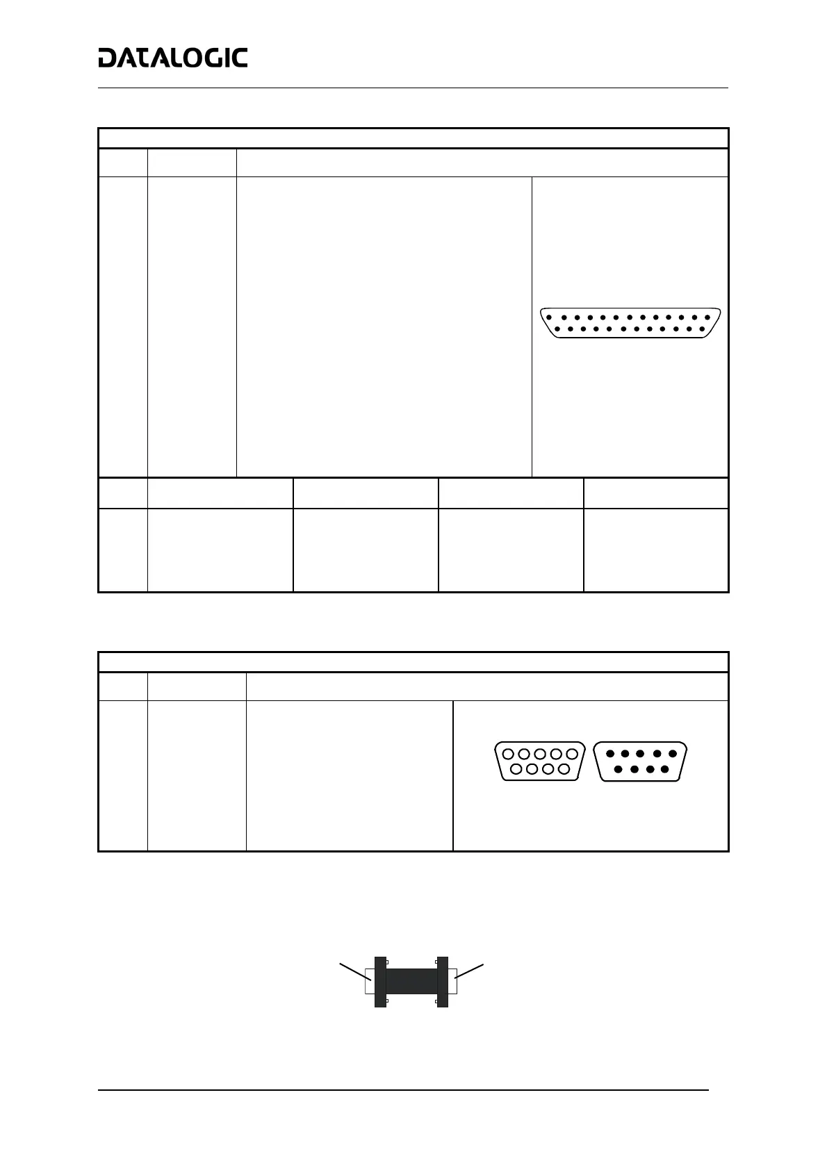
The details of the connector pins are indicated in the following table:
25-pin D-Sub Connector Pinout
Pin Name Function
1 Shield Internally connected by capacitor to chassis
20 RXAUX Receive data of auxiliary RS232 (referred to GND)
21 TXAUX Transmit data of auxiliary RS232 (referred to GND)
8 OUT 1+ Configurable digital output 1 – positive pin
22 OUT 1- Configurable digital output 1 – negative pin
11 OUT 2+ Configurable digital output 2 – positive pin
12 OUT 2- Configurable digital output 2 – negative pin
16 OUT 3A Configurable digital output 3 – polarity insensitive
17 OUT 3B Configurable digital output 3 – polarity insensitive
18 EXT_TRIG A External trigger (polarity insensitive)
19 EXT_TRIG B External trigger (polarity insensitive)
6 IN2A Input signal 2 (polarity insensitive)
10 IN2B Input signal 2 (polarity insensitive)
14 IN3A Input signal 3 (polarity insensitive)
15 IN4A Input signal 4 (polarity insensitive)
24 IN_REF Common reference of IN3 and IN4 (polarity insensitive)
9, 13 VS Supply voltage – positive pin
23, 25 GND Supply voltage – negative pin
14
1
25
13
25-pin male D-sub Connector
Pin RS232 RS485 Full-Duplex RS485 Half-Duplex
20 mA C.L.
(INT-30 with C-BOX 100 only)
2 TX TX485+ RTX485+
3 RX RX485+
4 RTS TX485- RTX485-
5 CTS RX485-
7 GND_ISO GND_ISO GND_ISO
see INT-30 instructions
* For 20 mA C.L. connections, GND is the same of the scanner power supply.
9-pin Lonworks Connector Pinout
Pin Name Function
1 Shield Cable shield
9 VS Supply voltage – positive pin
2 GND Supply voltage – negative pin
6 VS_I/O Supply voltage of I/O circuit
3 Ref_I/O Reference voltage of I/O circuit
4 SYS_ENC_I/O System signal
5 SYS_I/O System signal
7 LON A Lonworks line (polarity insensitive)
8 LON B Lonworks line (polarity insensitive)
5
1
9
6
Female
1
5
6
9
Male
9-pin Local Lonworks Connectors
Network Termination:
When building a local Lonworks system the network must be properly terminated by positioning a BTK-6000
terminator on the DS6300 master reader (BTK-6000 female side) and on the last slave reader (BTK-6000 male
side).
BTK-6000 Network Terminator
to Master
9-pin female
to Slave
9-pin male

 Loading...