Parts of the Reader
QUICK REFERENCE GUIDE
7
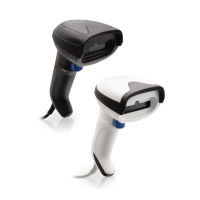
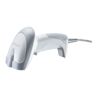
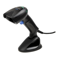
PARTS OF THE READER
1. LED 3. Scan Window
2. Cable Release Hole 4. Trigger
SELECTING THE INTERFACE TYPE
Upon completing the physical connection between the
reader and its host, proceed directly to Interface Selection
below for information and programming for the interface
type supported by the reader and scan the appropriate
bar code to select your system’s correct interface type,
according to your application.
For interfaces other than those
listed in this manual, see
the Gryphon™ I GD4500 Product Reference Guide (PRG),
available online at www.datalogic.com.
Interface Selection
The reader will support all the following host interfaces:
• RS-
232 STD
• RS-
232 WN
• IB
M46XX port 9b (a specific cable's required)
• USB H
ID POS
• USB T
oshiba TEC
• USB
(Keyboard, COM, OEM)
• USB
Composite (Keyboard + COM)
• USB
for Magellan Scanners
• Ke
yboard Wedge
 Loading...