EasyManua.ls Logo

Datalogic Matrix 120 - User Manual

Datalogic Matrix 120
17 pages
Print Icon
To Next Page IconTo Next Page
Loading...
Skip to content
Manuals+
User Manuals Simplified.
DATALOGIC Matrix 120 User Guide
Home » DATALOGIC » DATALOGIC Matrix 120 User Guide
Contents [ hide
1 DATALOGIC Matrix 120
2 INSTALLATION
PROCEDURE
3 Mounting
4 Electrical Connections
4.1 I/O Connections
5 Connector Pinouts
6 CONFIGURATION
6.1 Installing DL.CODE
7 TECHNICAL FEATURES
8 PATENTS
9 LASER SAFETY
10 File Downloads
11 References
12 Related Manuals

Other manuals for Datalogic Matrix 120

Questions and Answers

  • L
    leesamanthaAug 27, 2025
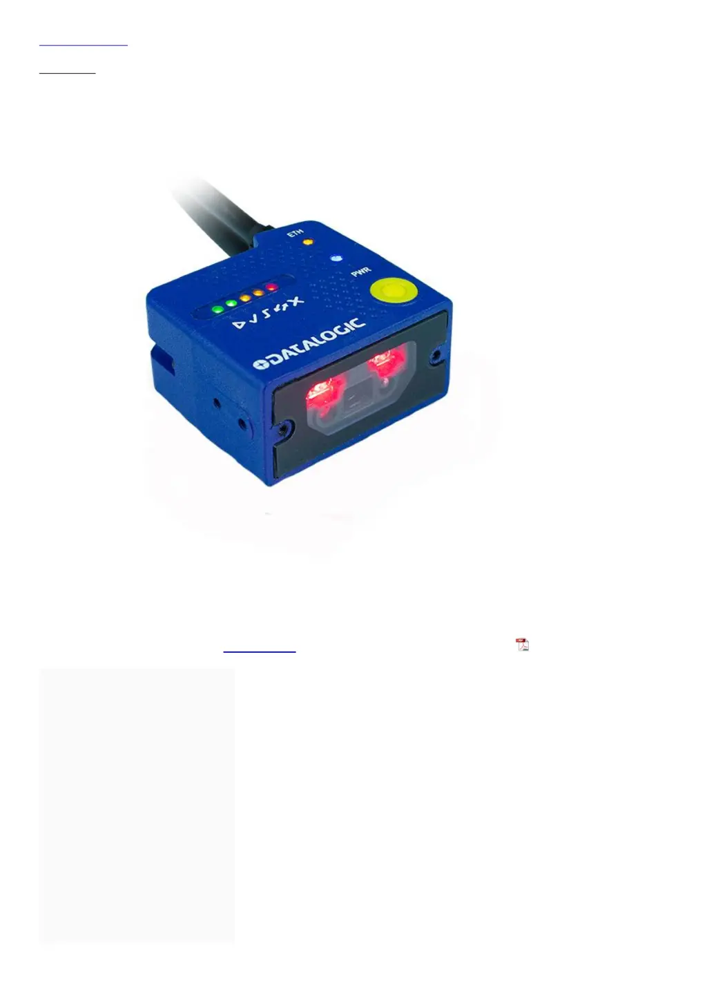
    Why Datalogic Scanner doesn't transmit results even when TRIGGER LED is blinking?
    • T
      terri04Aug 27, 2025
      If the TRIGGER LED on your Datalogic Scanner is blinking but no result is transmitted, verify the Code Collection parameters in the Reading Phase step and the Data Formatting parameters in the Data Formatting step.
  • M
    Mary ThomasAug 27, 2025
    What to do if the POWER LED is not lit on Datalogic Scanner?
    • J
      John MossAug 27, 2025
      If the POWER LED on your Datalogic Scanner is not lit, check the following: * Ensure the power is connected. * If using a power adapter (like PG6000), verify it's connected to the wall outlet. * If using rail power, check if the rail has power. * If using CBX, confirm it has power by checking the switch and LED. * Verify whether you are referring to the device/accessory cable or the CBX spring clamp connectors. * Measure the voltage either at pin 1 and pin 2 (for the 17-pin connector) or at the spring clamp Vdc and GND (for CBX).
  • R
    Randy JonesAug 25, 2025
    How to fix Datalogic Scanner when it is not transmitting data to the host?
    • L
      lindseylandryAug 26, 2025
      If your Datalogic Scanner is not transmitting anything to the host, consider these potential solutions: * Check the serial cable wiring to ensure it is correct. * If using CBX, make sure the RS422 termination switch is OFF. * Confirm that the host serial port settings are the same as the reader serial port settings. * In DL.CODE, you can configure the COM LED Function to indicate Main Serial Port TX or Main Serial Port RX under Device menu > Settings > Settings > LED Configuration.
  • G
    George ChambersAug 23, 2025
    Why is the data transferred to the host incorrect or corrupted from Datalogic Scanner?
    • S
      Sarah BrownAug 25, 2025
      If the data transferred to the host from your Datalogic Scanner is incorrect, corrupted, or incomplete, check the following: * Ensure the host serial port settings match the reader's serial port settings. * Verify the Header and Terminator String parameter settings in the DL.CODE Data Formatting step. * Check the various Message Field parameter settings in the DL.CODE Data Formatting step.

Summary

INSTALLATION PROCEDURE

Mounting

Procedure for physically mounting the Matrix 120 reader using a mounting bracket.

Electrical Connections

Details on making necessary electrical connections for the reader.

I;O Connections

Information on I/O connections using CAB-1011 and CBX, including NPN/PNP wiring.

Connector Pinouts

Pinout details for Power-Serial-IO and Ethernet connections of the reader.

CONFIGURATION

Installing DL.CODE

Steps to download, install, and run the DL.CODE software for reader configuration.

TECHNICAL FEATURES

Electrical Features

Details on power supply, consumption, and communication interfaces of the reader.

Environmental Features

Information on operating temperature, storage, humidity, and resistance ratings.

User Interface

Description of LED indicators and keypad button functionality for user interaction.

Software Features

Overview of readable code symbologies, operating modes, and configuration methods.

SAFETY AND COMPLIANCE

EMC and Power Supply Compliance

Guidelines for EMC compatibility and safe power supply connections.

Laser Safety

Information on the Class 1M laser source and safety precautions for use.

Regulatory Compliance (CE;FCC)

Details on CE marking directives and FCC rules for device operation and interference.

ADDITIONAL INFORMATION

File Downloads

Links to download user guides and other relevant files for the Matrix 120.

References and Related Manuals

List of external references, patents, and related product manuals for further information.

Datalogic Matrix 120 Specifications

General IconGeneral
Type2D Imager
Light SourceWhite LED
Aiming SystemLaser
Image SensorCMOS
Read Capability1D, 2D
Minimum Resolution0.1 mm
InterfaceUSB, RS-232, Ethernet
Operating Temperature0°C to 45°C
Storage Temperature-20°C to 60°C
Power Supply5V DC
Humidity90% non-condensing
CertificationsCE

Related product manuals