RAPID CONFIGURATION
12
P2X-SERIES™
Use the CAB-ETH-X-Mxx for the Ethernet connection to the host.
CBX500/CBX800 Pinout for P2x-Series™
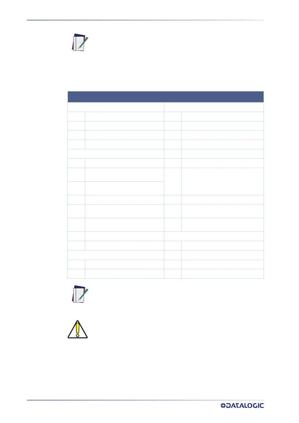
The table below gives the pinout of the CBX500/CBX800 terminal block connectors. Use
this pinout when the P2x-Series™ camera is connected using the CBX500/CBX800.
NOTE
The P2x-Series™ does not support sourcing power towards the CBX in
order to power I/O devices. These devices must be powered through the
CBX or from an external source.
CBX500/800 TERMINAL BLOCK CONNECTORS
Input Power Outputs
Vdc
Power Supply Input Voltage +
+V
Power Source - Outputs
GND
Power Supply Input Voltage -
-V
Power reference - Outputs
Earth
Protection Earth Ground
O1+
Output 1 +
O1-
Output 1 -
Inputs
O2+
Output 2 +
+ V
Power Source -External Trigger
O2-
Output 2 -
I1A
External Trigger A (polarity insensi-
tive)
O3A
CBX500: Strobe/Output 3 (Single Pin
Connection)
I1B
External Trigger B (polarity insensi-
tive)
- V
Power Reference - External Trigger
O3B
CBX500: Not Used
+ V
Power Source - Inputs
O3A
CBX800: Strobe + / Output 3+ (Opto-
isolated; See Note)
I2A
Input 2 + or - (polarity insensitive)
O3B
CBX800: Strobe - / Output 3- (See
Note)
I2B
Input 2 + or - (polarity insensitive)
RS232 Interface
-V
Power Reference - Inputs
TX
Transmit
Shield
RX
Receive
Shield
Network Cable Shield
SNGD
Signal Ground
NOTE
The strobe signal connection is shared with Output 3. Output 3 is active
only if the External Strobe is disabled. (Configure in VPM – Settings – Cam-
era – General)
CAUTION
Do not connect GND and SGND to different (external) ground references.
GND and SGND are internally connected through filtering circuitry which
can be permanently damaged if subjected to voltage drops over 0.8 Vdc.

 Loading...
