ELECTRICAL CONNECTIONS
36
P2X-SERIES™
POWER SUPPLY
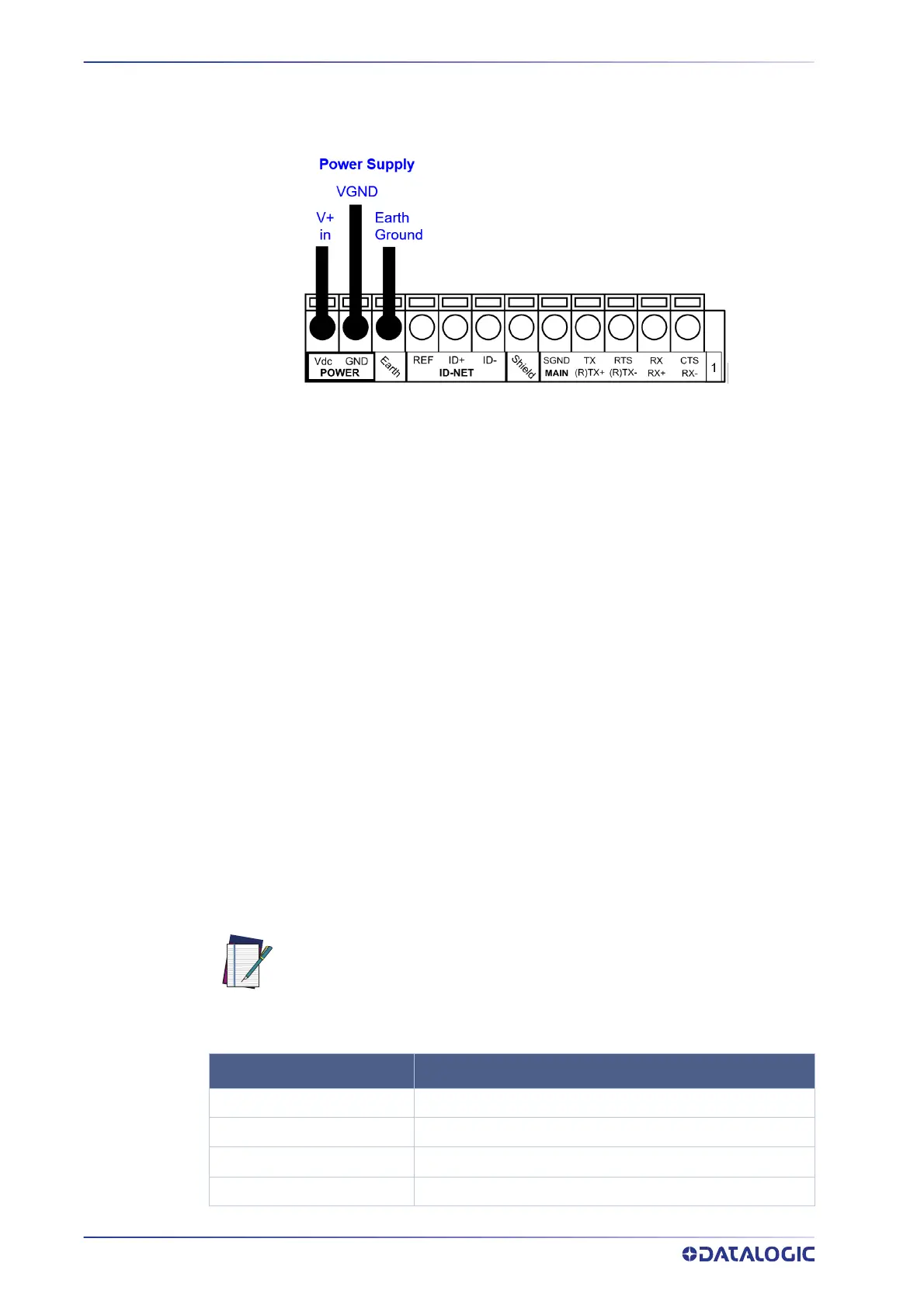
To power the camera and/or I/O devices through the CBX, power must be supplied to
the CBX500/800 spring clamp terminal pins as shown in Figure 2.
Figure 2- Power Supply Connections
The power must be between 10 and 30 Vdc only.
It is recommended to connect the device CHASSIS to earth ground (Earth) by setting the
appropriate jumper in the CBX connection box. See the CBX Installation Manual for
details.
INPUTS
There are two optocoupled polarity insensitive inputs available on the camera: Input 1
(Trigger) and Input 2, a generic input:
The Trigger is used to trigger the camera so it will acquire an image.
Input 2 can be used as a signal to a software task to perform an action.
The electrical features of both inputs are:
V
AB
= 30 Vdc max.
I
IN
= 10 mA (camera) + 12 mA (CBX) max.
The active state of these inputs are selected in software. Refer to the Camera Setup tab
and Discrete Input tool sections of the Impact Reference Guide.
An anti-disturbance filter is implemented in software on both inputs so that the default
minimum pulse duration is ≅ 0.5 milliseconds. This value can be increased or decreased
through the software parameter Debounce Filter. Refer to the Camera Setup tab section
in the Impact Reference Guide for further details.
These inputs are optocoupled and can be driven by both NPN and PNP type commands.
The connections are indicated in the following diagrams:
NOTE
Polarity insensitive inputs are full functionality even if pins A and B are
exchanged.
CBX500/800 FUNCTION
+V
Power Source - External Trigger
I1A
External Trigger A (polarity insensitive)
I1B
External Trigger B (polarity insensitive)
-V
Power Reference - External Trigger

 Loading...
