11. Digital I/O Setting Digital Output Lines Setting Output 6 Use = Redundancy.
NOTE
Only one Controller (the Working or the Protecting) will have the OUT-6
On. This output is used to inform the Host about which is the Active
Controller:
OUT-6 On = Controller is Active
OUT-6 Off = Controller is in Stand By
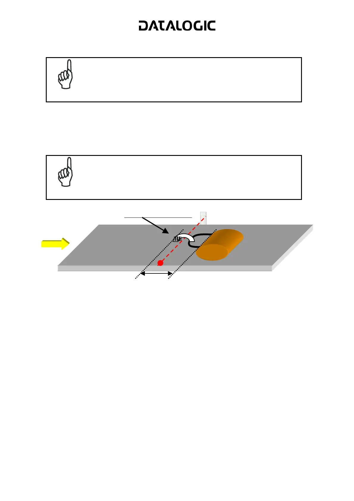
12. Operating Modes Minimum Distance Between Packs (mm) = 200.
13. Operating Modes Minimum Pack Length (mm) = 200.
14. Operating Modes Window Dimension (mm) = 200.
NOTE
This three parameters above are very important in order to avoid
Glitch and packs too short or too near not realistic as you can see in
the picture below.
200 mm
Glitch or
ack too short
15. Send the configuration to the Working Controller: Send with Options + Environmental
Parameters.
16. Save the configuration on the PC.
2.7.2 Master Protecting Controller REDS configuration
Starting from the Default, complete the Protecting Controller configuration as follow:
1. Load the Configuration of the Working Controller from the PC.
2. Change only the parameter: Redundancy Parameters Topology Redundancy =
Master Protecting.
3. Send the configuration to the Protecting Controller: Send with Options + Environmental
Parameters.
 Loading...