2.2 REQUIRED PARTS
Other than the various scanners used for the reading station, the following parts are necessary to
construct the redundancy station:
Name Description Part Number
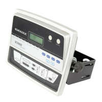
SC6000 SC6000-1200 Universal Controller, Ethernet 935701000
PWO-480 J-box power unit 110/230 VAC 24 V 480 W 93ACC1767
CAB-SC6013 25p cable SC6000 to PWO PWR/NET, 3 m
(for Power/Net connections)
93A051337
CAB-SC6003 25p cable SC6000 to PWO I/O, 3 m
(for Extended I/O connections)
93A051338
CAB-SC6103 9p cable SC6000 to PWO, 3 m
(for serial connections if used)
93A051294
CAB-PWO 03 17p cable PWO to PWO, 3 m
(for redundancy)
93A051295
BTK-8100 Bus terminator kit (5 pcs) 93ACC1090
CAB-8101 17-pin scanner/scanner connection cable 1.2 m 93A051020
CAB-8102 17-pin scanner/scanner connection cable 2.5 m 93A051030
CAB-8105 17-pin scanner/scanner connection cable 5 m 93A051040
PH-1 Photocell kit - PNP 93ACC1791
OEK-2 Optical Encoder (Cab 10 meters + Spring) 93ACC1770
2.3 REDUNDANT SYSTEM INSTALLATION
1. Install the two SC6000/PWO groups, each with its own Encoder and PS, using the cables and
accessories listed in the parts table (standard hardware configuration). See the relative product
Reference Manual.
2. Install the scanner branches distributed equally between the two PWOs. See the relative
product Reference Manual and see the paragraph
2.6 Redundancy Scanner Connections of
this manual.
3. Connect the CAB-PWO 03 Redundancy cable between the two PWOs.
4. Decide which SC6000/PWO group will be Working Controller and which will be Protecting
Controller. Consequently set the PWO-480 switches as shown in the table below.
Topology Role LON TERM IN3 REDUNDANCY SRC SEL
Working
ON ON PWR PWR
1 1 1 1 1 1
RE RE
STD STD
Protecting
ON ON PWR PWR
1 1 1 1 1 1
RE RE
REV REV
Scanners 8K TERM 8K BYP
8k only
ON ON OFF OFF
6k only
OFF OFF
ON ON
Both 6k and 8k
OFF OFF
OFF OFF
5. Power up the system and perform a Restore Default with Environmental Parameters on both
SC6000s: With Genius
Menu Bar
Device Menu
Send with Options
select
Default Parameters + Environmental Parameters
OK
6. Disconnect the Protecting Controller from the PWO.

 Loading...