DI-2108 Hardware Manual
Controls, Indicators, and Connections
10
D#: Digital port (0-6). Can also be used for specific WINDAQ functions (+25 Vmax).
D0 Event — WINDAQ Remote Event Marker (or general-purpose)
D1 Record — WINDAQ Remote Start/Stop (or general-purpose)
D2 Rate — Rate Input (or general-purpose)
D3 Count — Counter Input (or general-purpose)
D4 and D5 — General-purpose digital ports
D6 Ext Trig — External Trigger (or general-purpose)
+5V: +5V out. Max current = 100mA.
GnD: Ground.
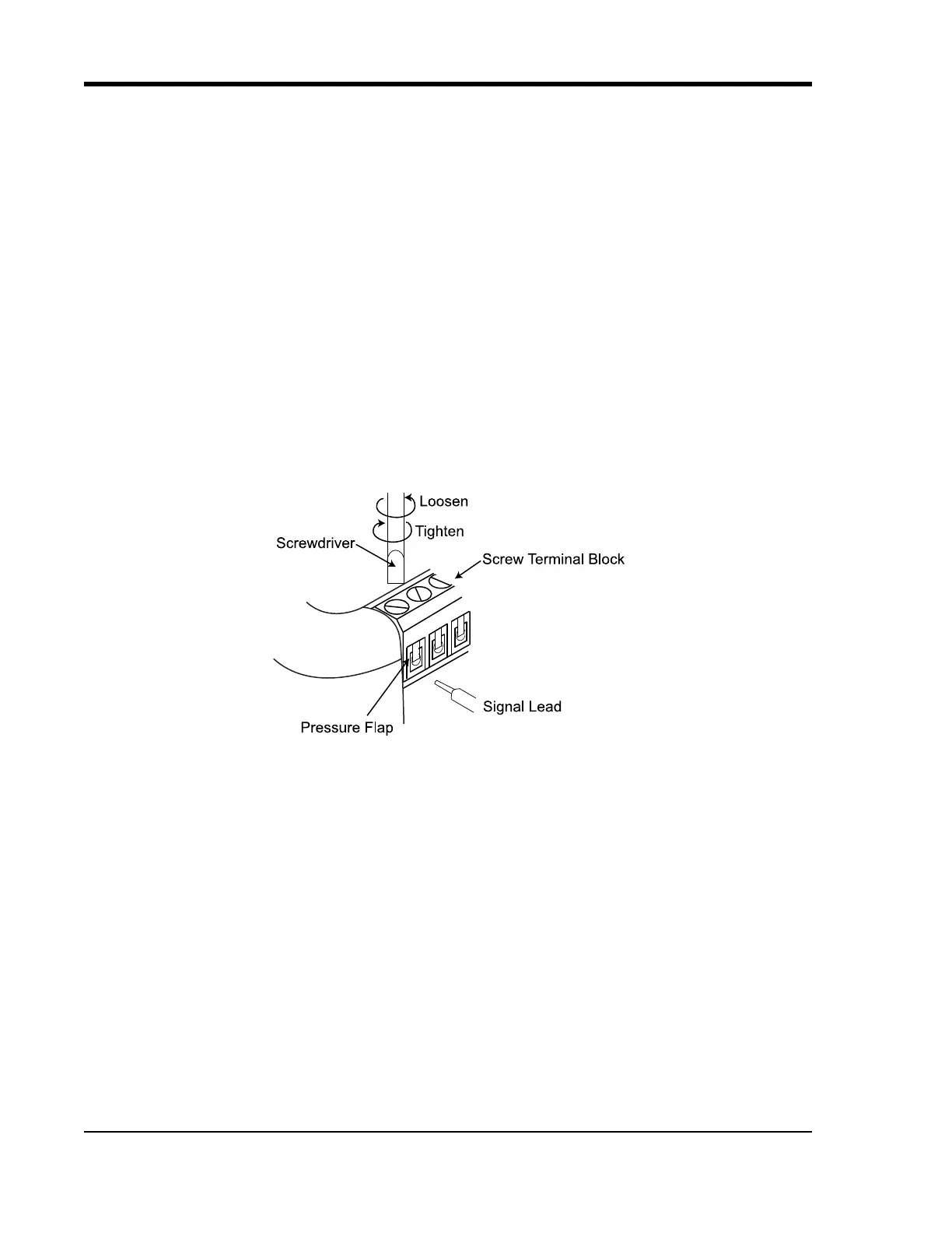
Connecting Signal Leads
Connect signal leads to the DI-2108:
1. Insert the stripped end of a signal lead into the desired terminal directly under the screw.
2. Tighten the pressure flap by rotating the screw clockwise with a small screwdriver. Make sure that the pressure
flap tightens only against the signal wire and not the wire insulation. Do not over-tighten.
3. Tug gently on the signal lead to ensure that it is firmly secured.
When an input signal is connected and WINDAQ Acquisition software is run, WINDAQ’s real time display immedi-
ately reveals the input waveform on your computer’s monitor.