3KP64 - 3.7
3000PLUS WITH 5D64 INSTRUCTION MANUAL V. SB.2
SETUP STAGE 2: INPUT RANGE INFORMATION
(
cont’d)
When the
3000PLUS
displays this . . . Do this . . .
Thus, if the actual full-scale range of the source transducer lies close to a
given nominal range value
, it is most “practical” to select the range just
below that nominal value. For example, if your actual transducer full-scale
range is 10 VDC, it is most practical to select a
nominal range of 7.5 VDC
(and NOT 10 VDC), since 10 lies with the “practical” range of “7.8000 -
10.3999.” Note also that the
highest “practical range” allows an actual
transducer input as high as 239.985 VDC.
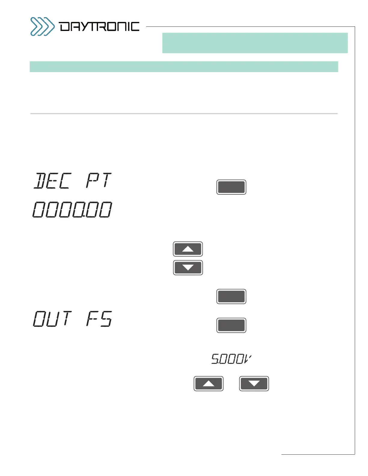
2.c. Press
2.d. You should now indicate the desired
DECIMAL-POINT PRECISION for
the instrument’s standard ±5-volt scaled output (Channel No. 1), for the
“auxiliary” DAC output (Channel No. 2), and for all setup values directly
relating to the instrument’s scaled engineering-units reading (including full-
scale reading, limit setpoint and hysteresis values, peak “defeat” thresh-
old,” tared output, and all calibration numbers expressed in units):
Pressing will cycle the decimal point to the
left.
Pressing will cycle the decimal point to the
right.
2.e. Then press
2.f. Press
2.g. The 3000PLUS instrument’s currently effective
FULL-SCALE OUTPUT IN
ENGINEERING UNITS
value will be displayed, alternating with
Use
and
as explained in Section 3.A to adjust the displayed number to equal the
desired full-scale output in engineering units (to the decimal-point preci-
sion specified in Step 2.f, above). This is the instrument reading that is to
correspond to a full-scale analog output of +5.000 volts. The initial (default)
value is “5000.”
(cont’d)
ST
and
RG
are lit.
3. FRONT-PANEL CONFIGURATION
AND CALIBRATION
The BLINKING DECIMAL
POINT (here shown to yield a
number precise to
hundredths)
will appear in the position to
which it was last set.
Daytronic Corporation
2211 Arbor Blvd. Dayton, OH 45439 • (800) 668-4745
Tel: (937) 293-2566 • Fax: (937) 293-2586 • www.daytronic.com