3KP64 - 3.10
3000PLUS WITH 5D64 INSTRUCTION MANUAL V. SB.2
Daytronic Corporation
2211 Arbor Blvd. Dayton, OH 45439 • (800) 668-4745
Tel: (937) 293-2566 • Fax: (937) 293-2586 • www.daytronic.com
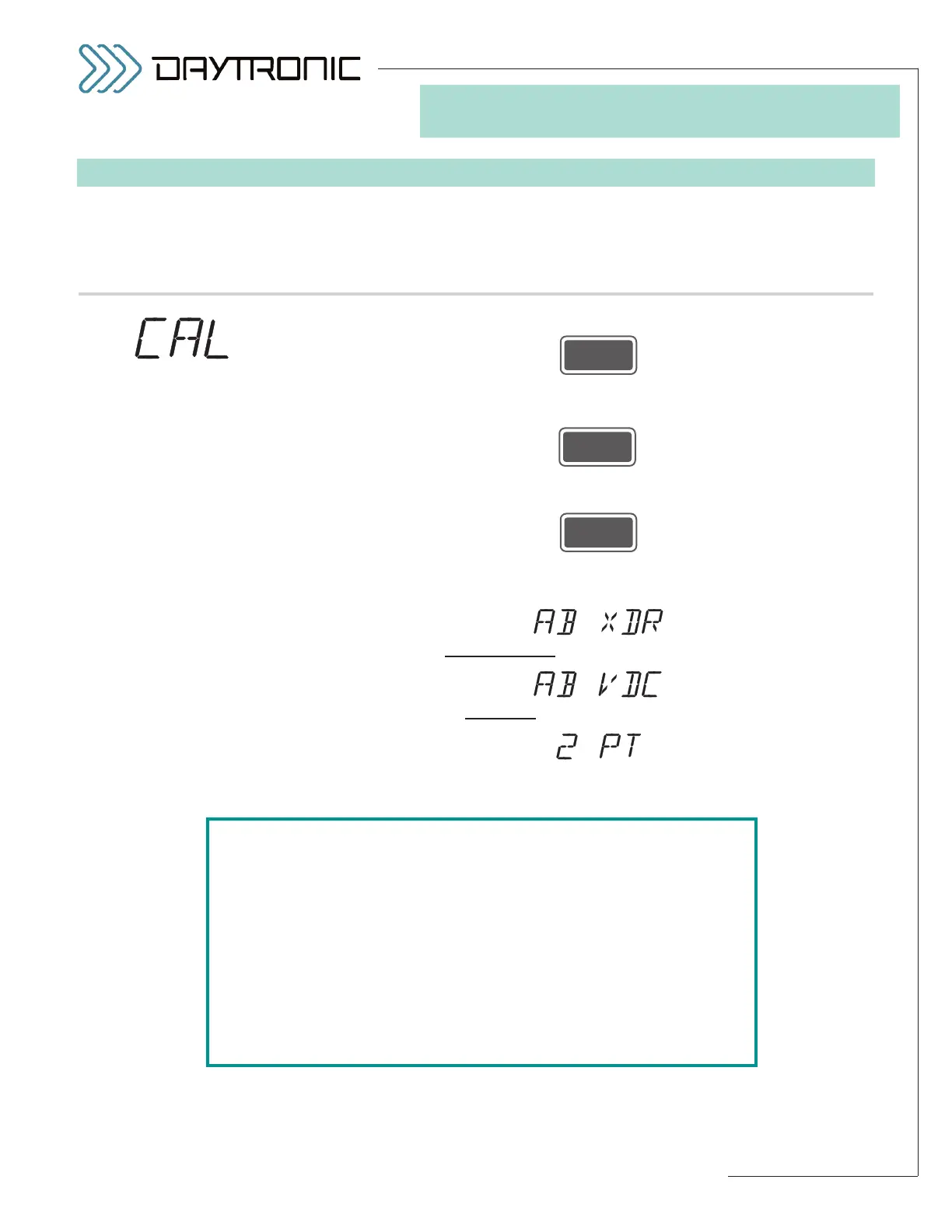
SETUP STAGE 4: CALIBRATION
When the
3000PLUS
displays this . . . Do this . . .
4.a. Press
4.b. The currently specified
CALIBRATION METHOD for the installed 5D64
module will be displayed. Press
repeatedly to cycle through the list of allowed values (shown left). When
the desired method is displayed, press
To continue with calibration, go to the subsection below for the calibration
method you have selected:
For
ABSOLUTE TR
ANSDUCER
CALIBRATION
, go to Section 4(AX), p. 3.11.*
For
ABSOLUTE V
OLTAGE CALIBRATION
, go to Section 4(AV), p. 3.17.*
For
TWO-POINT (DEADWEIGHT) CALIBRATION, go to Section 4(T), p. 3.20.
ST
and
CL
are lit.
3. FRONT-PANEL CONFIGURATION
AND CALIBRATION
5D64 CALIBRATION
SELECTIONS*:
AB XDR
(ABSOLUTE
TRANSDUCER)
AB VDC
(ABSOLUTE
VOLTAGE)
2 PT
(TWO-POINT)
*NOTE: For a general discussion of the three methods that may be
employed for 5D64 CALIBRATION, see Section 4.E of this manual.
For ABSOLUTE calibration, you will generally select
AB XDR
(“TRANSDUCER” mode) when the 5D64’s received input is to rep-
resent an analog of some parameter other than voltage—as would
be the case if the instrument were connected to a DC-to-DC LVDT
for measurement of physical displacement.
For ABSOLUTE calibration, you will generally select
AB VDC
(“VOLTAGE” mode) when the 5D64’s received input is to represent
voltage itself—as would be the case if the instrument were to be
used as a scaled voltmeter.