3KP64 - 3.22
3000PLUS WITH 5D64 INSTRUCTION MANUAL V. SB.2
Daytronic Corporation
2211 Arbor Blvd. Dayton, OH 45439 • (800) 668-4745
Tel: (937) 293-2566 • Fax: (937) 293-2586 • www.daytronic.com
SETUP STAGE 4(T): TWO-POINT CALIBRATION
(cont’d)
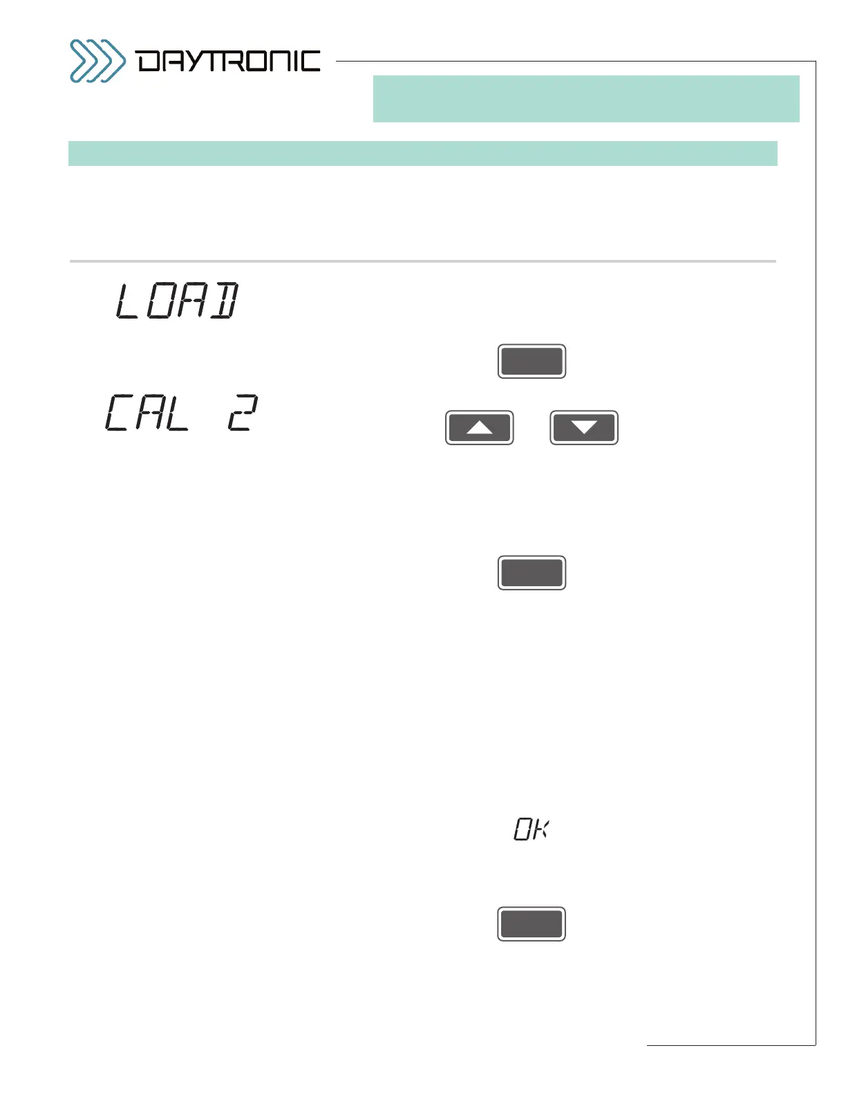
When the
3000PLUS
displays this . . . Do this . . .
4(T).c. Before you can enter your second calibration point (SPAN POINT), you
must establish your transducer “span” condition by applying a precisely
known amount of positively directed load between 80% and 100% of full
scale. When the transducer is positively “loaded,” press
4(T).d. Use
and
as explained in Section 3.A to adjust the displayed number (if neces-
sary) to the desired
SPAN POINT OUTPUT READING, expressed in
measurement units. The number you enter here will ordinarily be less
than or equal to the
FULL-SCALE OUTPUT IN ENGINEERING UNITS
which you entered in Step 2.g.
Then press
If you have
not changed the displayed number (alternating with “CAL 2”)
via the
UP/DOWN buttons, you should proceed directly to the optional
entry of the “–SYM” correction in Step 4(T).f, below.
If, however, you have changed the displayed span-point (
“CAL 2”) num-
ber, the 3000PLUS will calculate a new
MODULE SCALING FACTOR
(MSF)
, based on the entered reading, the current full-scale output set-
ting, and the
FULL-SCALE RANGE entered in Step 2.b—see Section 4.E
of this manual for more information on the
MSF parameter. An appro-
priate adjustment of the effective
MODULE INPUT OFFSET (MIO) ini-
tially determined in Step 4(T).b will also be calculated.
If the gain calculation yields an allowable gain value—and if the recalcu-
lated offset value is also allowed—those values will be applied to the
instrument’s output, and you will see a display of
alternating with the
“LIVE” SCALED OUTPUT READING.
If the reading that is now displayed corresponds sufficiently to your
desired
SPAN POINT OUTPUT READING, press
and proceed to the “RECAL?” query in Step 4(T).e, below.
(cont’d)