3KP64 - 3.25
3000PLUS WITH 5D64 INSTRUCTION MANUAL V. SB.2
Daytronic Corporation
2211 Arbor Blvd. Dayton, OH 45439 • (800) 668-4745
Tel: (937) 293-2566 • Fax: (937) 293-2586 • www.daytronic.com
SETUP STAGE 4(T): TWO-POINT CALIBRATION
(cont’d)
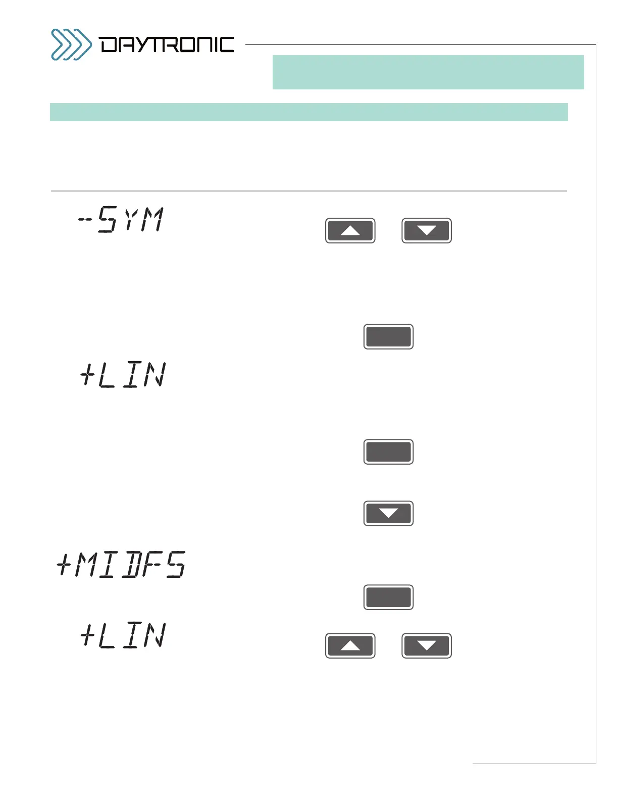
When the
3000PLUS
displays this . . . Do this . . .
4(T).h. Use
and
as explained in Section 3.A to adjust the displayed number until the
desired
NEGATIVE OUTPUT READING is obtained (correctly repre-
senting the present amount of negative load, expressed in measure-
ment units).
NOTE: You will not be allowed to change the displayed
number by more than 2% of its absolute value.
Then press
4(T).i. The 3000PLUS lets you apply a midscale POSITIVE LINEARITY COR-
RECTION
. Adjusting the 3000PLUS instrument’s POSITIVE LINEARITY
(LPN)
factor—a percentage of midscale output not greater than ±2%—is
useful in cases where the output linearity error increases and decreas-
es smoothly (with no inflections) with increasing values of input, as is
commonly the case with conventional LVDT sensors. If you want to
apply the positive correction factor, answer “YES” by pressing
and proceed to Step 4(T).j.
If no positive linearity correction is required, answer “NO” by pressing
and proceed to Step 4(T).l.
4(T).j. Before you can enter the correction, you must apply input loading in the
positive direction to approximately
half of the transducer’s nominal full-
scale rating. When this has been done, press
4(T).k. Use
and
as explained in Section 3.A to adjust the displayed number until the
desired
POSITIVE MIDSCALE OUTPUT READING is obtained (correct-
ly representing the present amount of positive load, expressed in mea-
surement units).
NOTE: You will not be allowed to change the displayed
number by more than 2% of its absolute value.