3KP64 - 3.28
3000PLUS WITH 5D64 INSTRUCTION MANUAL V. SB.2
SETUP STAGE 5: LIMITS
(
cont’d)
When the
3000PLUS
displays this . . . Do this . . .
5.e. Press
5.f. The instrument’s current
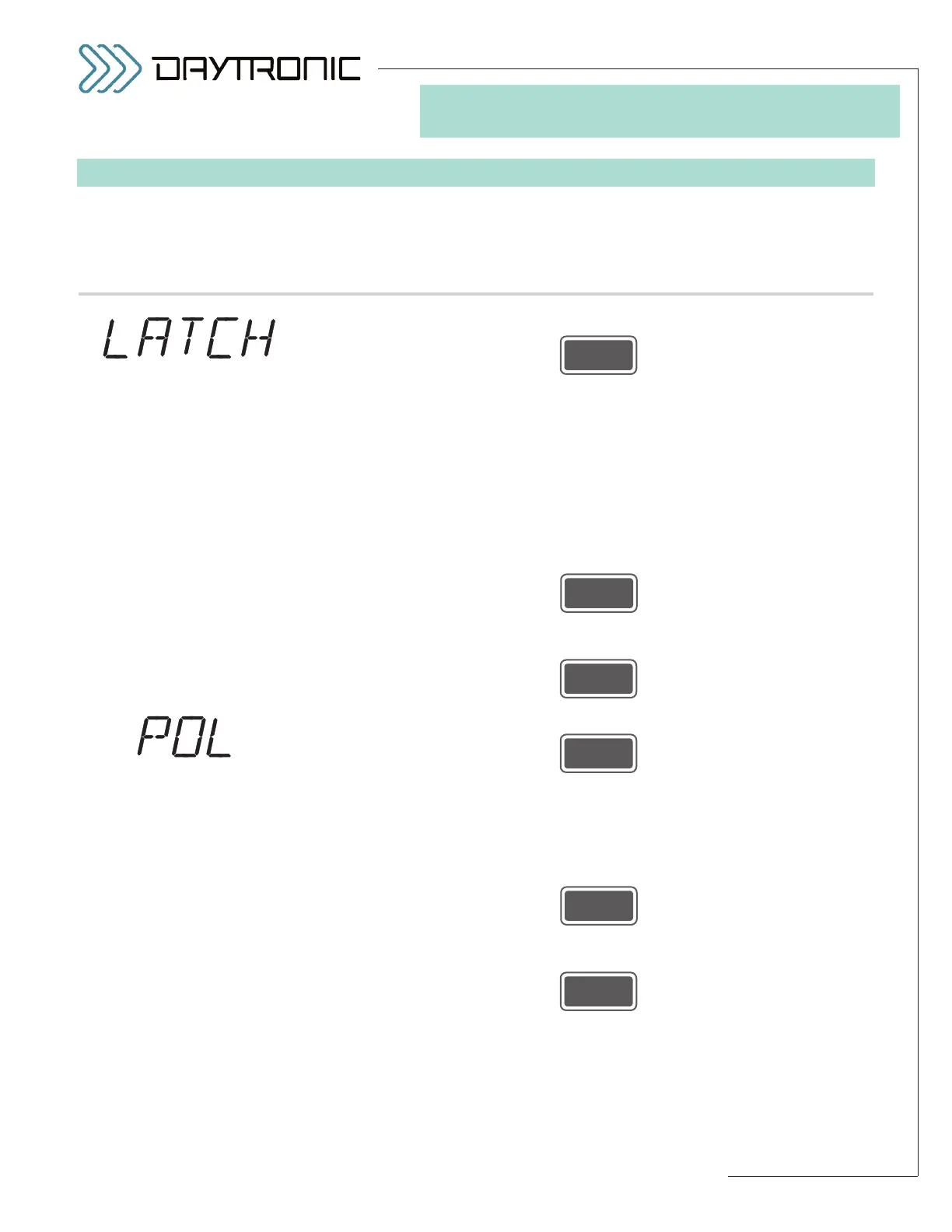
LIMITS LATCH MODE status will be displayed:
“ON” or “OFF.” In LATCHING mode (the “ON” state), when a high-limit or
low-limit violation is detected, that violation condition will remain in effect—
regardless of the subsequent behavior of the auxiliary output reading—
until limits are “released” (see Section 5.E for the different ways you can
accomplish this). When limits are NONLATCHING (the “OFF” state), any
detected limit violation condition will cease to occur as soon as the auxil-
iary output reading leaves the corresponding limit zone (or associated
hysteresis deadband).*
Press
to toggle between the two allowed states. When the desired latch mode
state is displayed, press
5.g. Press
5.h. The instrument’s current
LIMITS POLARITY status will be displayed: NOR-
MALLY CLOSED (“NC”) or NORMALLY OPEN (“NO”). This selection sets
the contact polarity of the 3000PLUS instrument’s limit output relays (for
LOGIC I/O connections, see Section 2.E).
Press
to toggle between the two allowed states. When the desired polarity state
is displayed, press
(cont’d)
ST
and
LM
are lit.
3. FRONT-PANEL CONFIGURATION
AND CALIBRATION
“LIMITS POLARITY”
SELECTIONS:
NC
NO
Daytronic Corporation
2211 Arbor Blvd. Dayton, OH 45439 • (800) 668-4745
Tel: (937) 293-2566 • Fax: (937) 293-2586 • www.daytronic.com
“LIMITS LATCH
MODE” SELECTIONS:
ON
OFF
* Latching also applies to the
“BETWEEN” (“OK”) limit zone.
See Section 5.E for a complete
discussion of 3000PLUS limit
monitoring.