3KP64 - 3.29
3000PLUS WITH 5D64 INSTRUCTION MANUAL V. SB.2
Daytronic Corporation
2211 Arbor Blvd. Dayton, OH 45439 • (800) 668-4745
Tel: (937) 293-2566 • Fax: (937) 293-2586 • www.daytronic.com
SETUP STAGE 5: LIMITS
(cont’d)
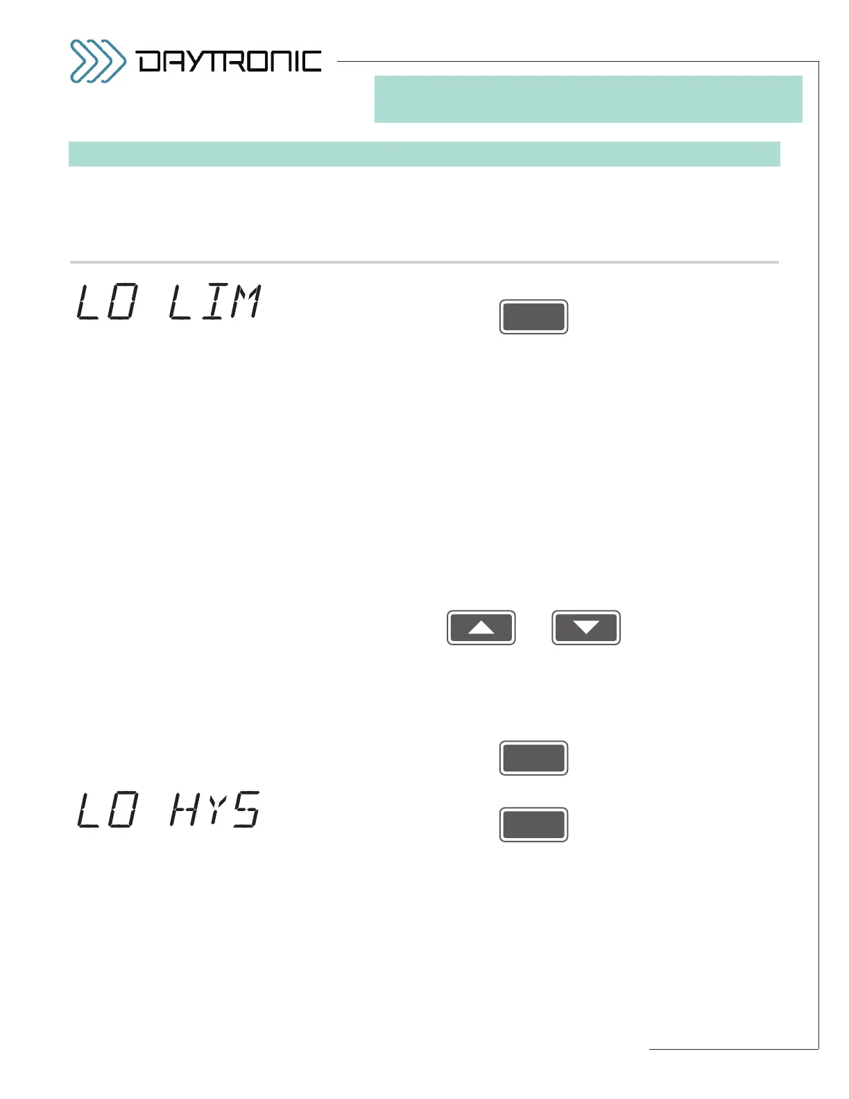
When the
3000PLUS
displays this . . . Do this . . .
5.i. Press
5.j. The instrument’s currently effective
LOW LIMIT setpoint value will be dis-
played (having the decimal-point precision specified in Step 2.f). The LOW
LIMIT setting and HIGH LIMIT setting (see below) define the 3000PLUS’s
three distinct LIMIT ZONES, as diagramed in Fig. 21 (Section 5.E)*:
• “LESS THAN” ZONE (“LO”): the reading for Channel 2 is less than the
current Low Limit
• “BETWEEN” ZONE (“OK”): the reading for Channel 2 is greater than or
equal to the current Low Limit and less than or equal to the current
High Limit
• “GREATER THAN” ZONE (“HI”): the reading for Channel 2 is greater
than the current High Limit
The “LESS THAN” or “GREATER THAN” zones may be effectively extended
for
nonlatching limits by means of a user-specified HYSTERESIS DEAD-
BAND (see below).
Use
and
as explained in Section 3.A to adjust the displayed number until the
desired limit value is obtained (expressed in measurement units).
NOTE:
You will not be allowed to enter a LOW LIMIT that is greater than the cur-
rent HIGH LIMIT (see below).**
Then press
5.k. Press
5.l. The instrument’s currently effective
LOW LIMIT HYSTERESIS value will be
displayed (having the decimal-point precision specified in Step 2.f). This
parameter lets you define a HYSTERESIS window (or “deadband”) immedi-
ately above the “LESS THAN” LIMIT ZONE defined by the current LOW
LIMIT setpoint value (see Fig. 21, Section 5.E). The hysteresis deadband is
to prevent low-level signal noise from toggling the low-limit relays on and
off while the reading of Channel 2 remains in the neighborhood of the set-
point.
(cont’d)
ST
and
LM
are lit.
3. FRONT-PANEL CONFIGURATION
AND CALIBRATION
* For a complete discussion of limit
monitoring, see Section 5.E. For
front-panel limit status indication,
see Section 1.D.
** Also, the absolute value of the
LOW LIMIT value should not be
greater than that of the
FULL-
SCALE OUTPUT IN ENGINEER-
ING UNITS
entered in Step 2.i.