3KP64 - 3.30
3000PLUS WITH 5D64 INSTRUCTION MANUAL V. SB.2
Daytronic Corporation
2211 Arbor Blvd. Dayton, OH 45439 • (800) 668-4745
Tel: (937) 293-2566 • Fax: (937) 293-2586 • www.daytronic.com
SETUP STAGE 5: LIMITS
(cont’d)
When the
3000PLUS
displays this . . . Do this . . .
Use
and
as explained in Section 3.A to adjust the displayed number until the
desired low limit hysteresis value is obtained (expressed in measurement
units). Enter a value of zero (“0,” “0.0,” etc.) to indicate no deadband.
NOTE: You will not be allowed to enter a negative number, or a number
that is greater than the
difference between the existing HIGH LIMIT and
LOW LIMIT values.
Then press
5.m. Press
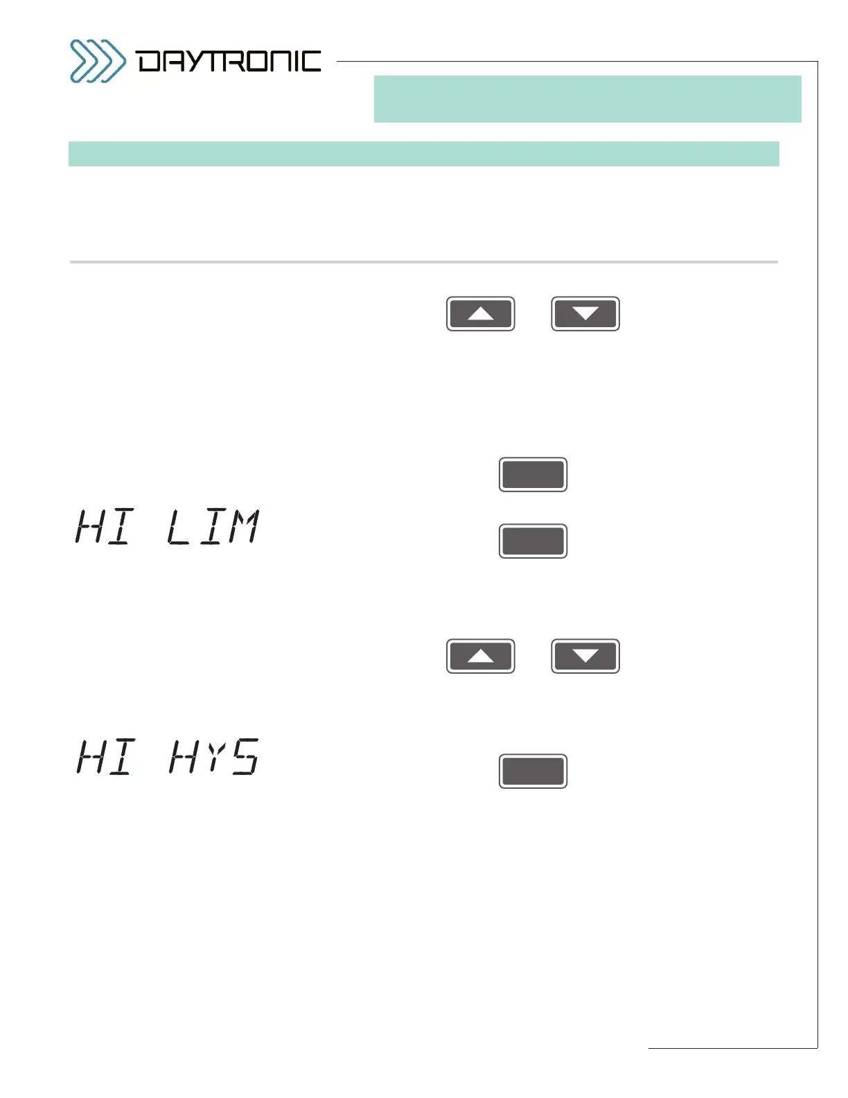
5.n. The instrument’s currently effective
HIGH LIMIT setpoint value will be dis-
played (having the decimal-point precision specified in Step 2.f). See Step
5.h, above, for an explanation of limit zones.
Use
and
as explained in Section 3.A to adjust the displayed number until the
desired limit value is obtained (expressed in measurement units).
NOTE:
You should not enter a HIGH LIMIT that is less than the current LOW LIMIT.*
5.o. Press
5.p. The instrument’s currently effective
HIGH LIMIT HYSTERESIS value will
be displayed (having the decimal-point precision specified in Step 2.f).
This parameter lets you define a HYSTERESIS window (or “deadband”)
immediately below the “GREATER THAN” LIMIT ZONE defined by the cur-
rent HIGH LIMIT setpoint value (see Fig. 21, Section 5.E). The hysteresis
deadband is to prevent low-level signal noise from toggling the high-limit
relays on and off while the reading of Channel 2 remains in the neighbor-
hood of the setpoint.
(cont’d)
ST
and
LM
are lit.
3. FRONT-PANEL CONFIGURATION
AND CALIBRATION
* Also, the absolute value of the
HIGH LIMIT value should not be
greater than that of the
FULL-
SCALE OUTPUT IN ENGINEER-
ING UNITS
entered in Step 2.i.