3KP64 - 3.32
3000PLUS WITH 5D64 INSTRUCTION MANUAL V. SB.2
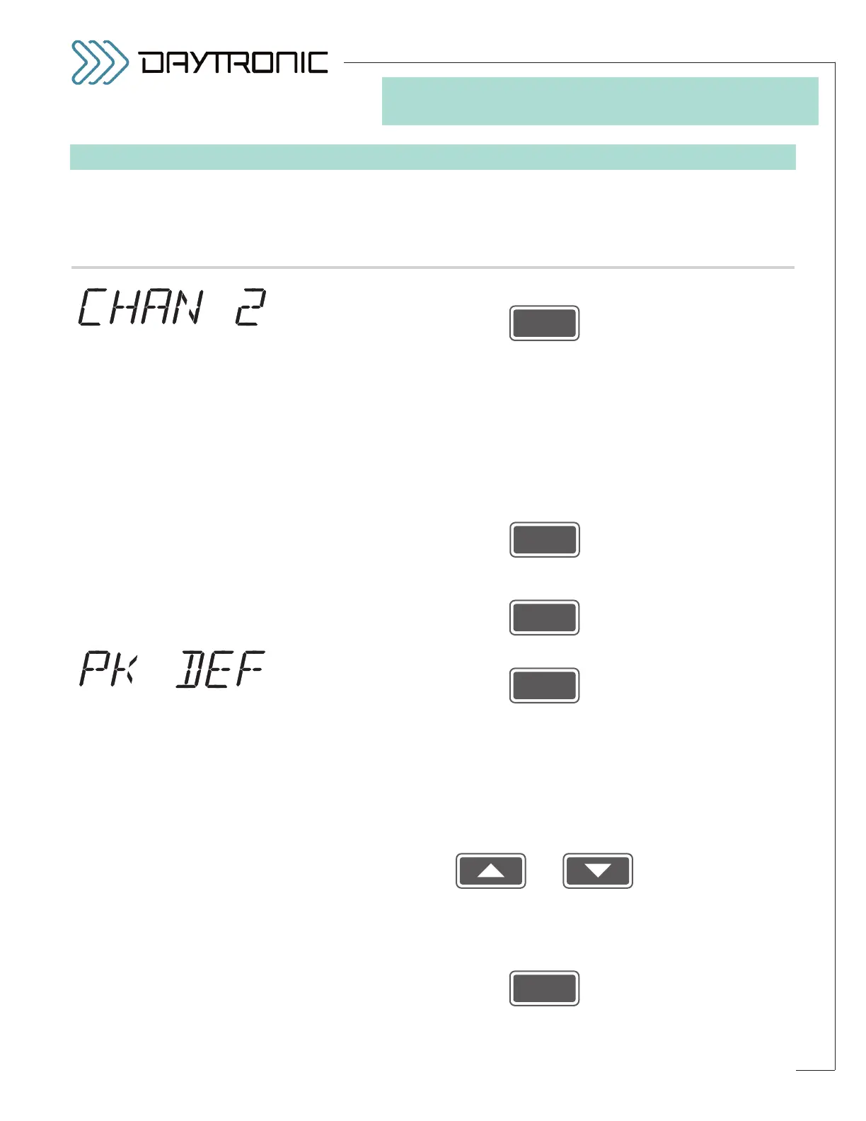
SETUP STAGE 6: “AUXILIARY” OUTPUT
When the
3000PLUS
displays this . . . Do this . . .
6.a. Press
6.b. The meter’s current
PEAK CAPTURE MODE will be displayed: POSITIVE
PEAK (“P PEAK”) or NEGATIVE PEAK (“N PEAK”). Here, “positive” peak
operation refers to the analog capture and hold of the
maximum (most
positive) excursion of the “auxiliary” DAC output (Channel 2), while “nega-
tive” peak operation refers to the capture of Channel 2’s
minimum (most
negative) excursion. The 3000PLUS will be placed in the selected mode
whenever peak capture is enabled by means of a logic input at the rear
PEAK terminal (for a complete discussion of peak capture operation, with
diagrams, see Section 5.B; for LOGIC I/O connections, see Section 2.E).
Press
to toggle between the two allowed modes. When the desired peak cap-
ture mode is displayed, press
6.c. Press
6.d. The instrument’s current
PEAK “DEFEAT” THRESHOLD will be displayed
(having the decimal-point precision specified in Step 2.f). By means of this
parameter, you can set up a “peak-defeat” input threshold in order to pre-
vent induced low-level signal noise from triggering a “HAVE PEAK” condi-
tion, when analog peak capture is enabled (see Fig. 18, Section 5.B).
Within the low-level deadband defined by this threshold, the output will
simply track the input, regardless of signal behavior.
Use
and
as explained in Section 3.A to adjust the displayed number until the
desired peak “defeat” threshold value is obtained (expressed in measure-
ment units).
NOTE: You will not be allowed to enter a negative number.*
Then press
(cont’d)
ST
and
PK
are lit.
3. FRONT-PANEL CONFIGURATION
AND CALIBRATION
“PEAK MODE”
SELECTIONS:
P PEAK
N PEAK
Daytronic Corporation
2211 Arbor Blvd. Dayton, OH 45439 • (800) 668-4745
Tel: (937) 293-2566 • Fax: (937) 293-2586 • www.daytronic.com
* Also, the threshold value should
not be greater than 20% of the
FULL-SCALE OUTPUT IN ENGI-
NEERING UNITS
entered in Step
2.i.