Getting Started
Section 1
DriveRack
®
PA
DriveRack
®
PA User Manual
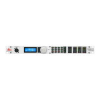
LCD Display
T
he backlit LCD display of the DriveRack
®
P
A provides the user with all of the vital processing
information of the DriveRack
®
PA including: signal routing, effect block editing and Wizard
Setup functions. The display will also notify the user if any internal clipping is taking place
w
ithin the unit. The following message will appear:
C
LIP.
Function Buttons
The function buttons of the DriveRack
®
PA allow direct access to all editing and navigating func-
tions of the DriveRack
®
PA. The functions of the aforementioned buttons are as follows:
<PREV PG> - is used to navigate back through the various pages of any module block.
<NEXT PG> - is used to navigate forward through the various pages of any module block.
<EQ> - is used to move to the EQ modules. Successive presses will move you through the
EQ modules in the input section and through EQ modules located in the output section.
<SUBHARMONIC> - This button is used to move to the Subharmonic Synthesizer module.
<XOVER> - is used to move to the Crossover module.
<FEEDBACK> - is used to move to the feedback elimination module.
<COMP/LIMITER> - is used to move to the Compressor or Limiter modules.
<DELAY> - is used to move to the Delay module.
<PROGRAM> - is used to enter program mode when pressed.
<UTILITY> - is used to access the the Utility menu.
<STORE> - is used to store any program changes.
<WIZARD> - is used to enter the Wizard section which includes: SYSTEM SETUP, AUTO EQ
WIZARD and AFS WIZARD.
Input Meters
The DriveRack
®
PA provides the user with two independent six segment Lightpipe
TM
input
meters that range from -30 to +20 dBu. These meters monitor the signal level right after the
input module.
Threshold Meters
The threshold meters indicate that the threshold level has been exceeded within the Limiter sec-
tion, and gain reduction may be taking place within the specific output channel.
Output Meters
The DriveRack
®
PA provides the user with six independent six-segment Lightpipe™ output
meters that range from -30 to +20 dBu.
Power Switch
The Power Switch tur
ns the DriveRack
®
P
A on and of
f.
Note: dbx Pr
ofessional Pr
oducts strong-
ly recommends that power amplifiers connected to the DriveRack
®
PA, should be powered
down prior to cycling the power on the DriveRack
®
PA.
For those of you that wish to jump right in, the following infor
mation has been pr
ovided to
act as a quick start guide for optimizing performance of the DriveRack
®
PA.
1.3 Quick Start
3