Copyright © 2005 Data Design Corporation Version 05.02.06
All rights reserved.
33
4.1.1 Analog Frequency Compensation Alignment
Generally the instrument will be fairly close to properly calibrated and the calibration
procedure will be used to make minor adjustments and verify operation on a scheduled basis.
The analog attenuator frequency compensation components are the most likely to drift. The
status of the alignment of these components can affect the gain over frequency. Therefore, this
alignment should be performed before any other step.
Adjusting the front end compensation is similar to adjusting the compensation of
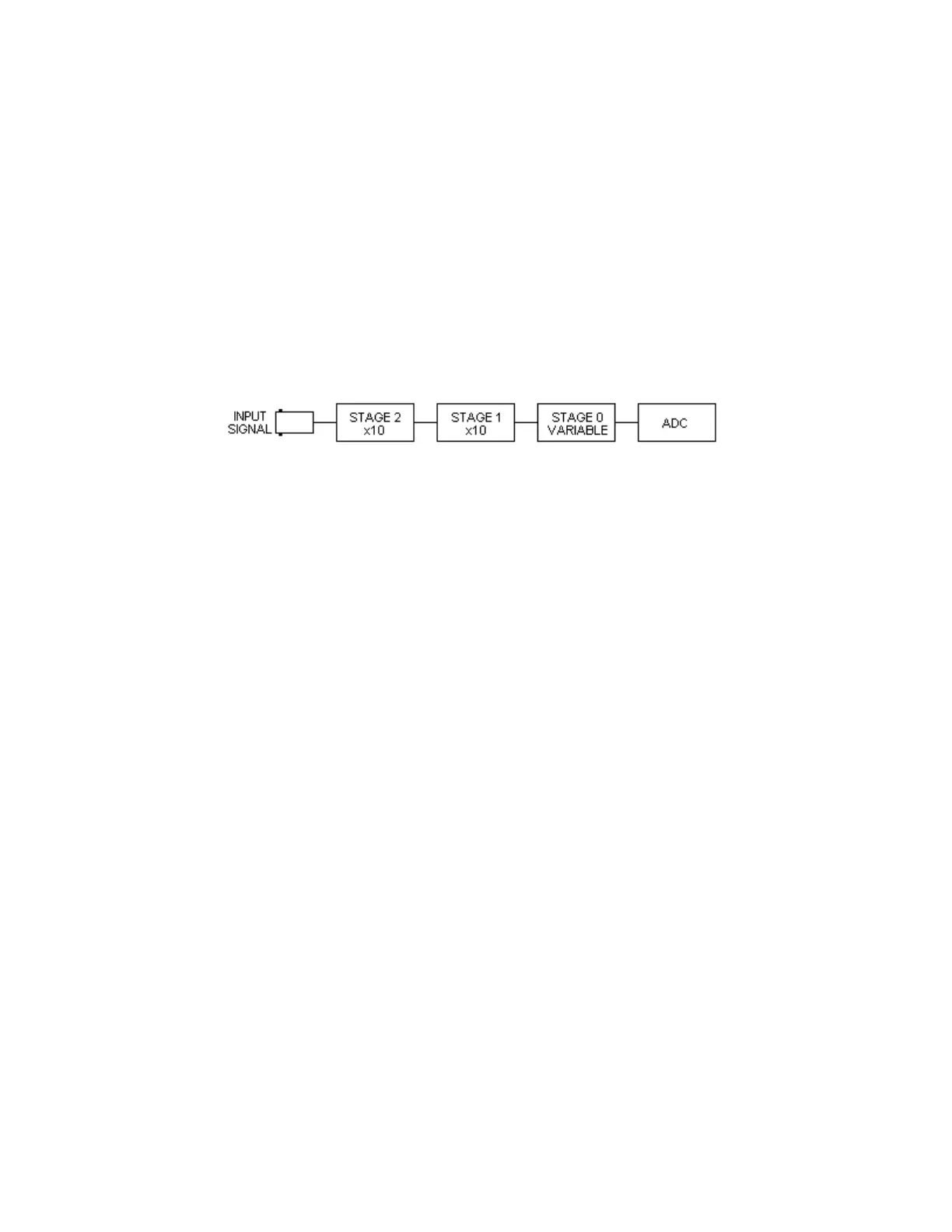
an oscilloscope probe. In fact, the TR122 high impedance attenuator is essentially two x10
oscilloscope probes connected in series and followed by a final attenuator and amplifier section.
Figure 4.2 is representative of the design.
Figure 4.2 TR122 Analog Attenuator
To adjust the compensation of the attenuator components, it is necessary to
identify and adjust each component independently of the others. Start by clicking on the Zero
Offset button to return the traces to midscreen. It may be helpful to display only one trace at a
time. All of these adjustments should be done in oscilloscope mode and are best done with a
horizontal setting and input frequency which provides the opportunity to observe step transitions
over relatively long periods of time. Oscilloscope frequency compensation is typically adjusted
at 1 KHz, and the transient recorder will not be much different except that a higher frequency
might be selected for display convenience. The display must be sufficient to observe affects on
step transitions over time and thus over a range of frequencies. It will become apparent that the
ability to apply test waveforms of various frequencies is also helpful in checking results.
Set the vertical controls for DC coupling. Apply a 100 mV to 200 mV peak to peak
square wave to the channel being adjusted. The amplitude is not important, but it should be
certain that the waveform has as square an edge as possible. Click on the Analog Alignment
button. The attenuator will adjust so that only the stage 0 attenuator is affecting the signal and a
message will display. Leave the message on the screen. Use a plastic alignment tool to adjust
the compensation capacitor furthest from the front of the unit. The alignment capacitors appear
through holes in the attenuator module printed wiring board behind each channel input connector
and offset towards the analog-to-digital converter integrated circuit (chip) for each channel.
They appear in the order shown in Figure 4.2 from the front panel connection side of the board
and towards the converter chip. Adjust the alignment for stage 0 until the signal displayed on the
oscilloscope screen is as accurate a representation of the incoming signal as possible with respect
to the shape of the rising and falling edges. Due to the limited bandwidth of the instrument, the
signal will never be square, but it will be close, particularly at low frequencies.
Note: Adjustment of the attenuator compensation capacitors requires a special tuning tool.
This tool is available from Data Design. Use of any other tool for this purpose will be
difficult and could damage the component.