Copyright © 2005 Data Design Corporation Version 05.02.06
All rights reserved.
15
2.3.1 Configuring Transient Record Memory
Beyond the basic setup which matches that of an oscilloscope, configuring the transient
recorder mode involves selecting a sample rate and memory geometry. Defining this
information is a rather manual step which is unique to a transient recorder, but it allows the user
to control and be aware of specific parameters of the recording. These parameters are critical
knowledge for some types of measurements and are generally not reported by an oscilloscope.
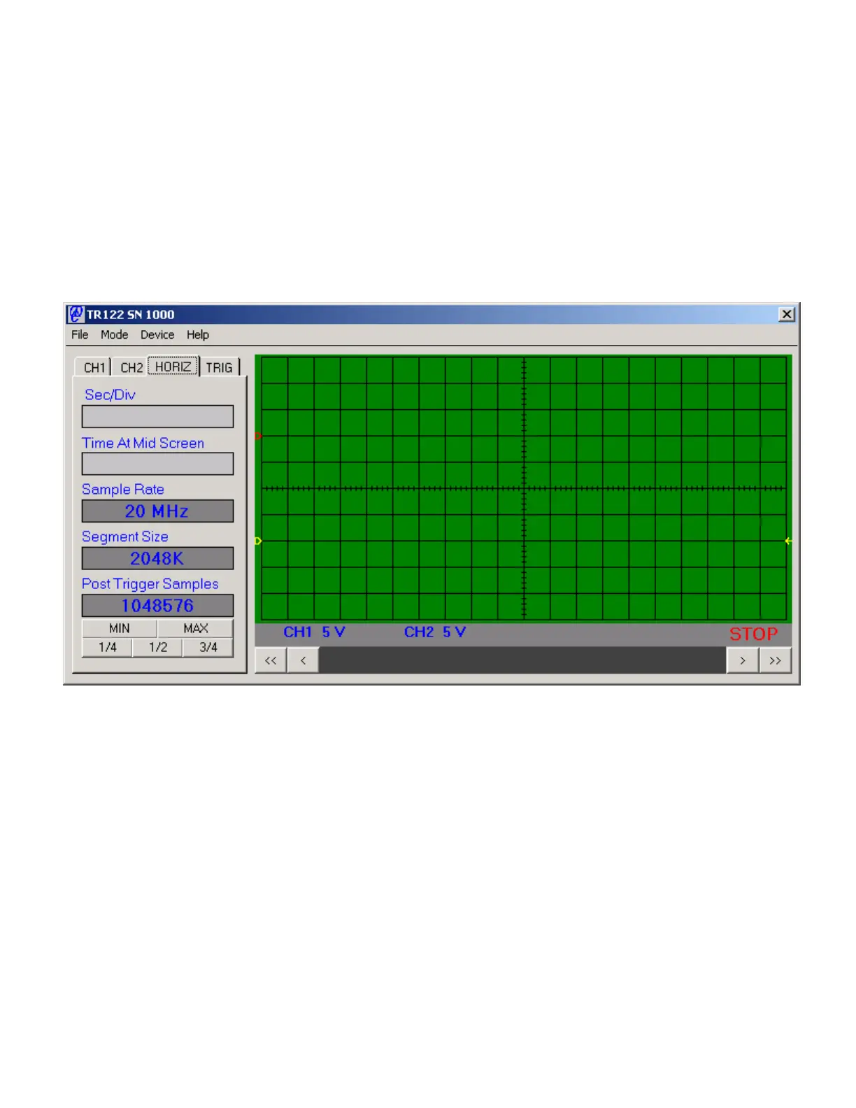
To allow control of these parameters, the HORIZ tab control in transient recorder mode will
appear as in Figure 2.6 below.
Figure 2.6 TR122 Memory Geometry Controls
The all important Sample Rate control is self explanatory to transient recorder users.
This control will generally be adjusted based on the frequency characteristics of the input signal
being viewed and by trading off recorded signal detail with the length of time which can be
stored in the instrument sample memory. When selecting a sample rate (measured in MHz or
Million Samples Per Second (MS/s)), keep in mind that the bandwidth of the TR122 analog
circuitry is always 100 MHz, and the roll off of the pass band is not steep. Any incoming signal
with a frequency component greater than half the sample rate can potentially appear misleading
when displayed due to aliasing, an important digital signal processing mathematical concept
which must be understood for successful use of a transient recorder or a digital oscilloscope.
Because the input bandwidth is 100 MHz, the potential for aliased information in the display is
limited when the full 200 MS/s sample rate is used. However, the effect can become pronounced
at lower sample rates.