22
5.1 ELECTRICAL CONNECTIONS FOR 24V MODELS
Execute the wiring following the directions of “Table 1” and diagrams on page 23.
WARNINGToensureanappropriatelevelofelectricalsafetyalwayskeepthe230Vpowersupplycablesapart(minimum4mm
intheopenor1mmthroughinsulation)fromlowvoltagecables(motorspowersupply,controls,electriclocks,aerialandauxiliary
circuitspowersupply),andfastenthelatterwithappropriateclampsneartheterminalboards.
WARNINGConnecttothepowersupply230V~±10%50Hzthroughamultipoleswitchoradifferentdevicethatcanensure
multipoledisconnectionfromthepowersupply,withacontactopeningof3mm.
WARNING Toconnecttheencodertothecontrolpanel,useonlyadedicatedcable3x0,22mm
2
.
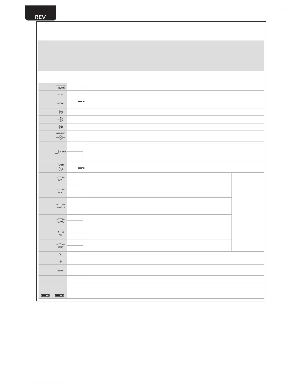
Table 1 “terminal board connections”
1-2 +24V powersupplyoutputforauxiliarydevices200mA
3-4
22V~transformerpowersupplyinput
5-6
24V batterypowersupplyorphotovoltaicaccumulatorGreenEnergyinput(followcarefullypolarity
indications).
7-8
Operator1output
9
Connectionofmotorsmetallicparts
10-11
Operator2output(ifpresent)
12-13
24V max15Woutputforopengatefix/flashingwarninglight(ifP052=0/1)orcourtesylight(ifP052>1)
14-15
14 (-)
“Boost”outputforelectric-lock,max1xart.110(ifP062=0),24Vpulseoutput,max5W(ifP062=1),
step by step (if P062=2), electro-brake output for not self-locking operators (if P062=3), output for
electric-lockpowersupplyviaexternalrelay(ifP062=4),outputforelectro-magnetspowersupplyfor
barriers(ifP062=5)ortemporizedoutput(ifP062>5).
15 (+)
16-17 24V Flashinglightoutputmax15Wart.Lumy/24A/S
18-19
18 - N.C.
Input6FCC1.IfitintervenesitstopsM1closing.If unused, short circuit.
Iftheinstallationrequiresdifferentcomman-
dsand/oradditionaltothestandard,you
can configure each input to the required
rate.
Refer to Chapter
“Advanced Programming”.
19 - Com
20-21
20 - N.C.
Input5FCA1.IfitintervenesitstopsM1opening.If unused, short circuit.
21 - Com
22-23
22 - N.C.
Input4PHOTO1.Whenenabled(seeparameterP050 in the table), activation of
PHOTO1provokes:aninversionofdirection(duringclosing),thearrestofthemo-
vement(duringopening),preventthestart(gateclosed).If unused, short circuit.
23 - Com
24-25
24 - N.C.
Input3SAFETY.Ifactivated,itcausestheinversion.SeeP055andP056onthepara-
meterstable.If unused, short circuit.
25 - Com
26-27
26 - N.O.
Input2PED.Ifactivated,itopensmotornr.1only.
27 - Com
28-29
28 - N.O.
Input1START.Incaseofinterventionitprovokes:theoperatoropeningorclosing.It
mayoperateas“inversion”mode(P049=0)or“stepbystep”mode(P049=1).
29 - Com
30 Aerialsignalinput
31
Groundaerialinput
32-33
32 (+)
DE@NETmainsinput(unusedatthemoment)
33 (-)
CON 1 230V~±10%(50/60Hz)powersupplyinput
J5 J9
EncoderselectionJumper:
•Aposition=operatorswithencoder(remindtosetP029=0)
•Bposition=operatorswithoutencoder(remindtosetP029=1)
AB AB