Dedicated Micros ©2009
12
EcoSense
Installing the EcoSense Unit
This procedure shows the sixteen camera input version.
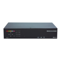
Step 1 Connecting Video
The unit supports up to 4, 8 or 16 connected Video Inputs (dependant on model) via the 75Ω BNC
connectors. Connect cameras to the video inputs, starting from input 1.
5.12
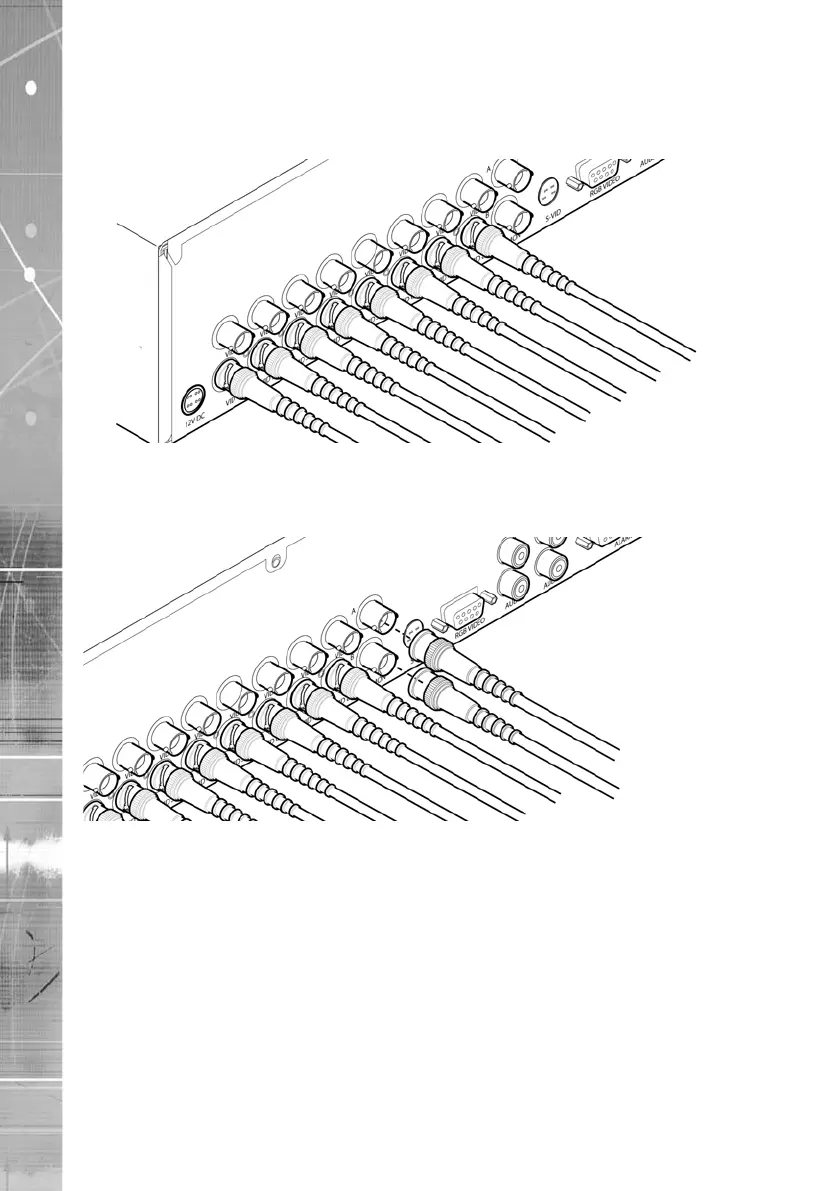
Step 2 Monitor
The unit supports a main monitor via ‘Mon A’ and a spot monitor via BNC labelled ‘Mon B’.
A monitor can also be connected via the S-Video or RGB Video outputs.