7679433.01 (3-06/17) 18
INSTALLER Section (en)
18. ANNUAL SERVICING
If the boiler was operating, wait for the combustion chamber and pipes to cool down.
Before commencing any maintenance operations, make sure the boiler is disconnected from the power supply. After servicing,
reset the original operating parameters of the boiler if they were changed.
Do not clean the boiler with abrasive, aggressive and/or easily ammable substances (such as petrol, acetone, etc.).
To optimise boiler efciency, carry out the following annual controls:
• Check the appearance and airtightness of the gaskets of the gas and combustion circuits. Replace any worn seals with new
original spares;
• Check the state and correct position of the ignition and ame-sensing electrodes;
• Check the state of the burner and make sure it is rmly xed;
• Check for any impurities inside the combustion chamber. Use a vacuum cleaner to do this;
• Check the pressure of the heating system;
• Check the pressure of the expansion vessel;
• Check the fan works correctly;
• Make sure the ue and air ducts are unobstructed;
• Check for any impurities inside the siphon (for condensation boilers);
• Check the magnesium anode, where present, for boilers tted with storage boilers.
It is advisable not to use the service cap at the base to empty and clean the siphon. Remove the siphon from inside the boiler
and clean it with a jet of water. Fill the siphon with clean water and put back in place, making sure that it is properly connected.
18.1 COMBUSTION PARAMETERS
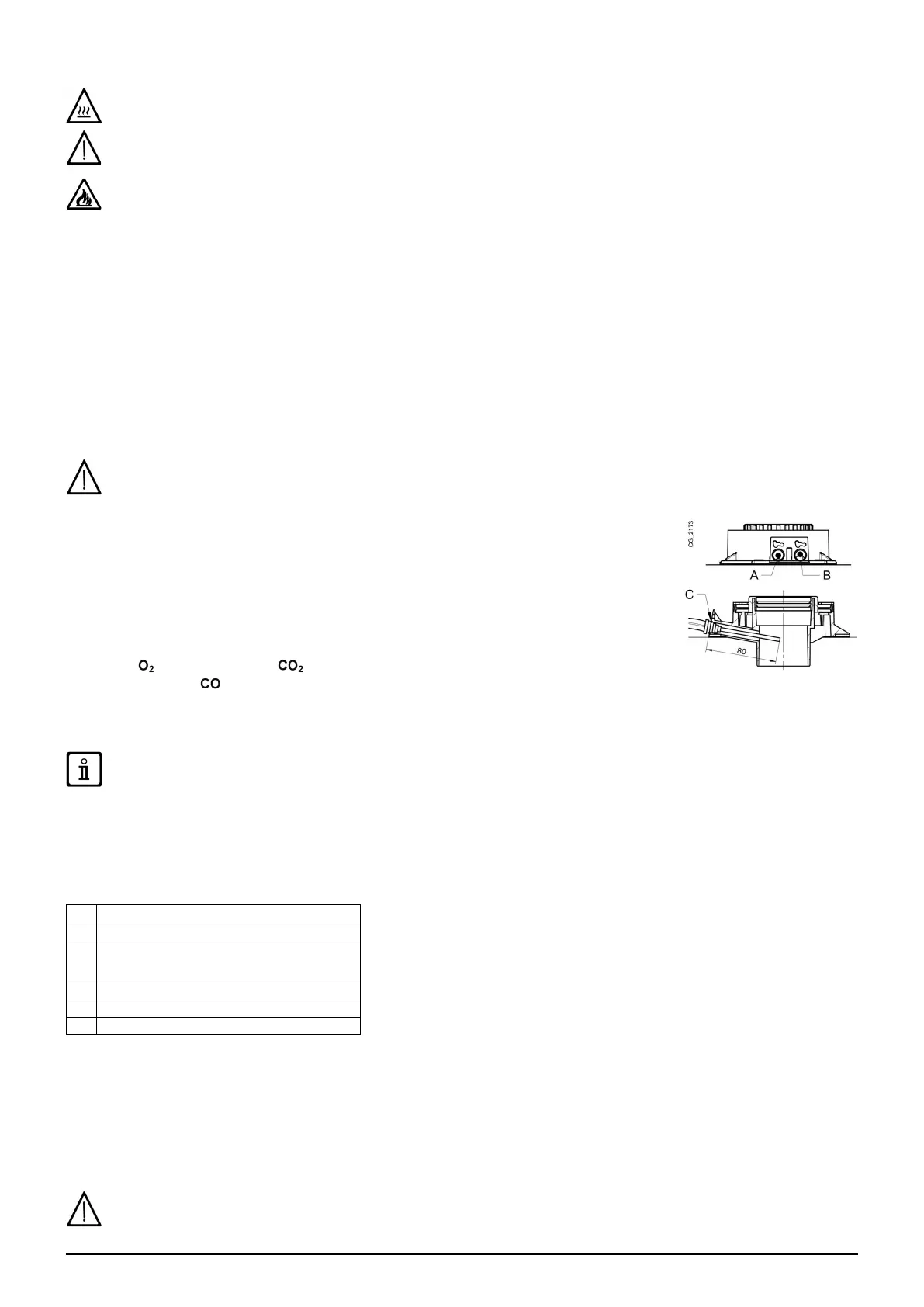
To measure combustion efciency and the toxicity of the products of combustion, the boiler is tted
with two dedicated test points. One connection point is connected to the ue gas discharge circuit
(A), and allows monitoring of the quality of the combustion products and the combustion efciency.
The other is connected to the combustion air intake circuit (B), allowing checking of any recycling of
the combustion products in case of coaxial pipelines. The following parameters can be measured
at the connection point on the ue gas circuit:
• temperature of the combustion products;
• oxygen (
) or carbon dioxide ( ) concentration;
• carbon monoxide (
) concentration.
The temperature of the comburent air must be measured on the test point located on the air intake ue (B) by inserting the
measurement sensor by about 8 cm (C).
To enable the " CHIMNEY SWEEPER" consult section 12.3.
18.2 HYDRAULIC UNIT
For special areas, where the water is harder than 20 °F (1 °F = 10 mg calcium carbonate per litre of water), install a polyphosphate
dispenser or an equivalent treatment system, compliant with current regulations.
LEGEND - "SECTION" F
A DHW exchanger xing screw
B DHW priority sensor with lter
C
Boiler/system drain tap
(C-1 & C-2: access to tap C - bottom of boiler)
D Boiler / system lling tap
E DHW temperature NTC probe
F Heating circuit water pressure sensor
18.2.1 CLEANING THE COLD WATER FILTER
The boiler is tted with a cold water lter located on the hydraulic assembly ( B). To clean, proceed as follows:
• Drain the domestic hot water system.
• Remove the nut on the DHW priority sensor unit
• Pull out the ow sensor and its lter.
• Remove any impurities.
When replacing and/or cleaning the O-rings on the hydraulic assembly, only use Molykote 111 as a lubricant, not oil or grease.