25
22. Slide the blanking plates between the
perpendicular fixing battens and the ridges of the
baseplates (38-A and 38-B). The must be fitted
flush with the edges of the baseplates.
They are fixed in position later on when the
mounting rails are attached.
8980P201
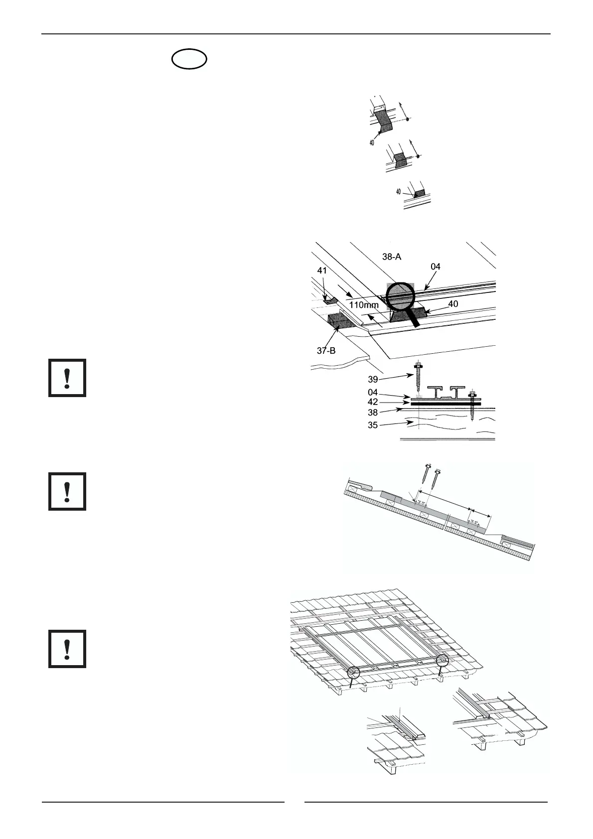
23.
On the ridges of the baseplates (38-A and 38-B)
measure 110 mm from the bottom edge and
mark a line. Remove the protective film from the
butyl strips (42) of the mounting rails (04) and
place the bottom mounting rails (04) precisely in
position and aligned flush on the ridges of the
baseplates (38-A and 38-B) as shown in Fig.
8980P201.
8980P202
24. Check that the blanking plates (40) are correctly
seated and fix the mounting rail (04) through the
pre-drilled holes to the perpendicular fixing
battens (37) using sealing screws (39).
Note:
The butyl strip is highly adhesive – once the
mounting rail is in place, its position cannot be
adjusted.
It is important that the butyl strip (42) is between
the ridge and the mounting rail at the point where
the screw passes through.
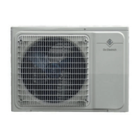
25. Fix the top mounting rails (04) in the same
manner observing the spacing illustrated.
Note:
The mounting rails (04) must be aligned
horizontally.
26. Remove the protective film from the self-
adhesive taper-section sealing strips (43) and
stick the sealing strips to the two side cover
plates (33).
Note:
The perpendicular edge should be on the
outside.
On rooves with a shallow pitch, also fit sealing
strips to the top edge of the top cover plates (33-
A and 33-B).
GB
~ 1800 mm
04
110 mm
8980N471
33-A
33-B
42
8980N
49
9