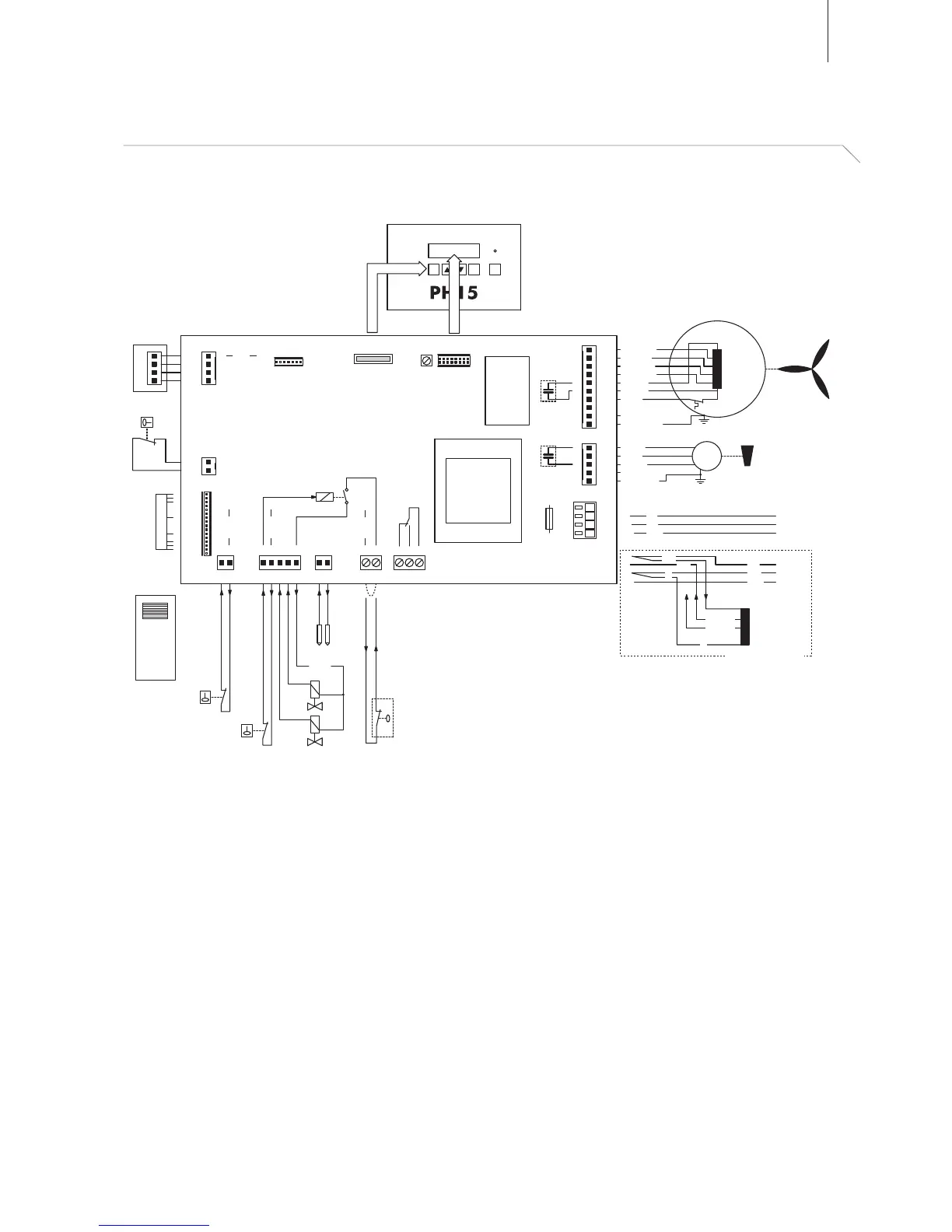
EasyManua.ls Logo

Defensor PH15 - Appendix; Wiring diagram

Defensor PH15
48 pages
Print Icon
To Next Page IconTo Next Page
To Previous Page IconTo Previous Page
Loading...
41
10 Appendix
10.1 Wiring diagram
B1, B2 Ionisation electrodes
B3 Level switch
F1 Fuse control board (1.25 A, slow acting)
M1 4-step fan
M2 Centrifuge motor
P1 Potentiometer display contrast
S1 Safety switch
S2 Leakage sensor (option)
S3 Micro switch carriage
X14
X15
X17
+5V
4
3
2
1
U1
P1
T1
T2
B3
B1 B2
X5
F1
M1
M2
X21
X9
X9
7 1
X10
2 1
1
+24V
X12
2 1
X6 X5
1 2 1 2 3
+24V
X13
5 4 3 2 1
+24V
+24V
X1
L1
L
N
PE
X3
1
2
3
5
4
X16
1
1
10
St. 1 (ws)
St. 2 (rt)
St. 3 (gu)
C2 (bn)
C1 (ge)
St. 4 (sw)
N (bl)
8
PE
PE
PE (gn/ge)
X4
1
2
3
5
6
4
7
8
9
10
ESC Enter I / 0
1.25 AT
S1
C (bn)
P (bl)
N (sw)
PE (gn/ge)
L1
L
N
PE
L
N 230 VAC
PE
L1
L
N
PE
L
N 100 VAC
PE
M
M
110V
110V
230V
230V/410mA
230V/240mA
N
N
N
S2
Y1
Y2
Display
Keypad&LED
Steuerprint PH15
300000382.000
Index XX
Art.Nr. XXXXXXX
U3
U2
S3
U1 Internal humidity sensor
U2 Radio receiver (option)
U3 External radio humidistat (option)
T1 Transformer control board
T2 Transformer 100 V version
X5 Error contact, max. 250 VAC
X9 Programming interface
Y1 Inlet valve
Y2 Inlet valve (safety valve)
100 V version only

Table of Contents

Related product manuals