Menu Value Details
5900 I Genset L1 current
5910 U Busbar L1-L2 voltage
5920 f Busbar frequency
5930 Input 102 The value received by analogue input 102.
5940 Input 105 The value received by analogue input 105.
5950 Input 108 The value received by analogue input 108.
5960 P total consumed The total power produced in the power management system.
5970 P total available
The additional power that the power management system could supply without starting more
gensets.
*Note: P1, P2 and P3 are identical. For example, P1 can be used as an input to a switchboard instrument, while P2 can be an
input to a PLC.
Available power transducer setup example
To set up transducer 66 to transmit the available power (0 to 10 MW) as a 4 to 20 mA signal:
In menu 5973, for Set point, select 4-20mA. For Transducer A, select Transducer 66.
In menu 5975, select the minimum value (this corresponds to 4 mA), that is, 0 kW.
In menu 5974, select the maximum value (this corresponds to 20 mA), that is, 10000 kW.
NOTE These values are also available through Modbus.
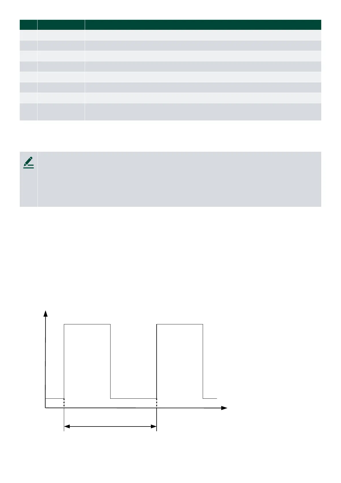
2.2 PWM duty cycle
2.2.1 Duty cycle
The PWM signal has a frequency of 500 Hz ±50 Hz. The resolution of the duty cycle is 12 bits, which gives 4095 output
levels. The output is an open collector output with a 1 kΩ pull-up resistor.
The low level of the signal is between 0 and 0.5 volts, and the high level is between 5.7 and 6 volts.
Time
Voltage
0 0.5 V
5.7...6 V
0 100 % duty
cycle
Options E F
AGC-4 Mk II 4189341277C EN Page 9 of 10
 Loading...


