MTR-3 Installation Instructions
DEIF A/S Page 12 of 51
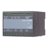
Connection 4u (3W4)
Three-phase – four-wire connection with
unbalanced load
Connection of input/output modules
Connect the module contacts as specified on the label. Examples of labels are given below and
describe modules built in the device.
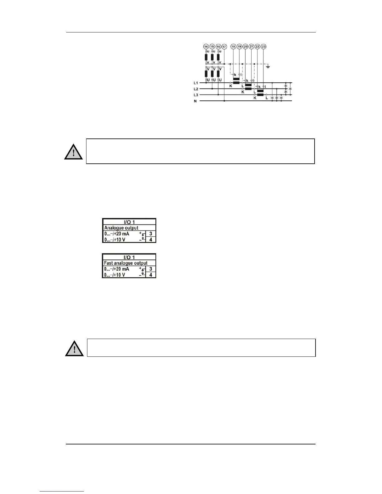
Analogue output module with analogue
output, proportional to measured qua
ntities. The outputs may be either short- or
open-circuited. They are electrically insulated
from each other and from all other circuits.
(Example of analogue output 1).
Fast analogue output module with analogue
output, proportional to measured quantities.
The outputs may be either short- or open-
circuited. They are electrically insulated from
each other and from all other circuits.
(Example of analogue output 1).
Communication connection
The MTR-3 is equipped with one standard serial (RS485) communication port and one service
communication port (USB).
Connect the communication line by means of the corresponding terminals. Connection
information is stated on the instrument label. Connector terminals are marked on the label on the
upper side of the instrument.
The USB connector is positioned on the bottom side of the instrument under removable plastic
cover. For driver installation, the below note. The instrument will establish USB connection with
the PC approx. 5 seconds after physical connection to the USB port.
More detailed information about communication specifications is available in the data sheet.
The USB communication port is NOT galvanically insulated and can be used
ONLY UN-connected to aux. supply and power inputs!
Check the module features that are specified on the label, before connecting
module contacts. Wrong connection may cause damage or destruction of