MTR-3 Installation Instructions
DEIF A/S Page 26 of 51
Explanation of basic concepts
Sample factor − M
V
A meter measures all primary quantities with sample frequency which cannot exceed a certain
number of samples in a time period. Based on these limitations (65 Hz·128 samples) a sample
factor is calculated. A sample factor (M
V
), depending on frequency of a measured signal, defines
a number of periods for a measurement calculation and thus a number of harmonics considered
in THD calculations.
Average interval − M
P
Due to readability of measurements from communication, an average interval (M
P
) is calculated
with regard to the measured signal frequency. The average interval (see “Average interval” on
page 16) defines the refresh rate of displayed measurements based on a sampling factor.
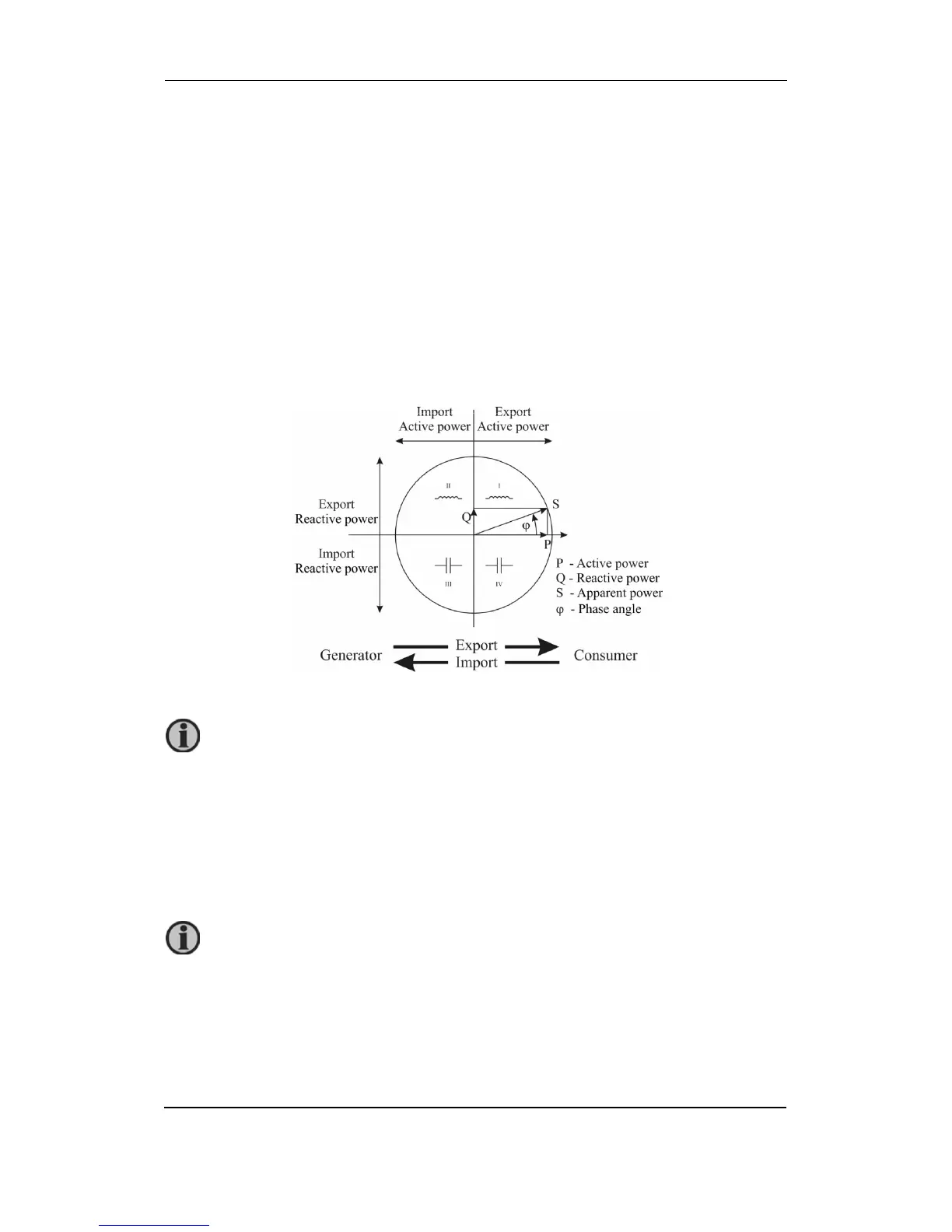
Power and energy flow
The figure below shows a flow of active power, reactive power and energy for 4u connection.
Calculation and display of measurements
This chapter deals with capture, calculation and display of all supported quantities of
measurement. Only the most important equations are described; however, all of them are shown
in chapter 8, “Appendix B: Calculations and equations” on page 36 with additional descriptions
and explanations.
view. This means that a consumer using energy will be exporting power. It is
possible to change export/import definition via the M-Set, by changing the energy
flow direction.
more detailed information, see “Survey of supported measurements regarding
connection mode” on page 23.