Do you have a question about the Deif MTR-3 and is the answer not in the manual?
Document's objective is to assist users with first steps of installing and using the unit.
Describes the document's organization into chapters for simplicity.
Outlines DEIF's responsibility and user obligations for installation and operation.
Advises on protecting terminals from static discharges during installation.
Highlights risks of working with dangerous currents and voltages during installation.
Explains symbols and terms used throughout the document.
Alerts users to potentially dangerous situations and their consequences.
Lists essential checks before switching on the device.
Provides guidance on proper disposal of electrical and electronic equipment.
Lists the items included in the product package.
Explains various symbols used in the installation instructions.
Details the purpose and features of the measuring transducer.
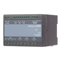
Shows a diagram of the transducer and labels its parts.
Describes the ports for communication and status indicators.
Explains how to connect the auxiliary power supply.
Describes the connection and limits for voltage inputs.
Details the connection and limits for current inputs.
Explains the function and application of the device.
Lists all measurements the device can perform.
Details different electric connection types supported.
Introduces the chapter on connecting the transducer.
Describes how to install the device on a DIN rail.
Explains how to connect voltage and current inputs.
Details various electrical connection configurations.
Details single-phase connection setup.
Describes three-phase balanced load connection.
Details three-phase unbalanced load connection.
Explains direct three-phase connection.
Describes three-phase balanced load connection.
Details three-phase unbalanced load connection.
Explains how to connect I/O modules.
Describes serial (RS485) and USB communication ports.
Details the RS485 serial communication setup.
Explains the USB communication setup and driver installation.
Provides a summary of communication connection options.
Details how to connect the device to auxiliary power.
Introduces the configuration options for the transducer.
Describes the software tool for monitoring and configuration.
Explains how to manage devices within the network.
Covers modifying various parameters of the instrument.
Explains how to capture and process live measurement data.
Guides on updating the instrument's firmware.
Illustrates the M-Set software interface for configuration.
Outlines the steps for modifying instrument settings using M-Set.
Describes essential transducer settings like connection and communication.
Explains how to identify and locate the device.
Defines the refresh rate for measurements.
Allows selection of units for temperature display.
Details the function for calculating maximum demand.
Illustrates the thermal function for MD calculation.
Sets a threshold for PF and PA measurements.
Sets a threshold for power calculations.
Defines the voltage level for synchronisation.
Explains methods for calculating reactive power.
Emphasizes the importance of correct connection settings.
Defines measurement support based on connection settings.
Crucial for accurate measurements and calculations.
Affects alarms, outputs, and recording ranges.
Used for alarms and defines valid frequency range.
Allows manual change of energy flow direction.
Influences power readings and sign if reversed.
Introduces communication settings for RS485 and USB.
Defines RS485 network parameters.
Defines Modbus table for measurements and settings.
Describes USB connection and driver installation.
Provides information on serial numbers and M-Set access.
Details how to set and modify user passwords.
Explains the process for changing existing passwords.
Describes how to disable password protection.
Notes the need to reset energy meters after parameter changes.
Explains how to define an active tariff.
Defines minimal energy display and influences pulse output.
Details the programmability of analogue outputs.
Sets the measured parameter for the analogue output.
Defines the full-scale ranges for analogue outputs.
Describes setting break points for output curves.
Sets the averaging interval for analogue output measurements.
Explains the functionality of the fast analogue output module.
Describes the functions assignable to relay outputs.
Configures energy counters for pulse output.
Provides guidance on setting pulse parameters.
Assigns alarm outputs to trigger relays.
Enables/disables output relays via software settings.
Configures recording and storage of 16 alarms.
Explains how to reset energy counters, MD values, and alarms.
Introduces the chapter on device measurements.
Lists all measurements supported by the device.
Details different electric connection types.
Details measurements based on connection type.
Lists fundamental electrical measurements.
Details measurements related to individual phases.
Details measurements between phases.
Covers energy counter readings and active tariff.
Lists maximum demand values for currents and powers.
Explains how sample factor is calculated.
Defines the averaging interval for measurements.
Illustrates power flow direction and definitions.
Details how measurements are captured and displayed.
Explains RMS voltage measurement and calculation.
Explains RMS current measurement and calculation.
Details calculation methods for power.
Explains network frequency calculation.
Mentions energy counter availability.
Refers to measurements of MD values.
Describes THD calculation and measurement technique.
Explains Modbus enablement via RS485 or USB.
Describes Modbus protocol for network operation.
Lists Modbus registers for actual measurements.
Lists measurements using IEEE 754 standard.
Details normalized measurement registers.
Lists registers for fast response normalized measurements.
Lists actual measurements for Version 2.
Details normalized measurements for Version 2.
Covers user passwords and command registers.
Includes location, connection mode, and input ranges.
Details communication parameters like baud rate and parity.
Covers energy counter parameters, dividers, and tariff selectors.
Configures output type, parameters, and breakpoints.
Manages alarm settings, parameters, and functions.
Explains the format and interpretation of different data types.
Defines symbols used in calculations and equations.
Lists formulas for voltage, current, and power calculations.
Presents formulas for active, reactive, and apparent power.
Explains formulas for current, phase, and phase-to-phase voltage THD.
Provides formula for price in tariff.
| Brand | Deif |
|---|---|
| Model | MTR-3 |
| Category | Transducer |
| Language | English |