MTR-3 Installation Instructions
DEIF A/S Page 39 of 51
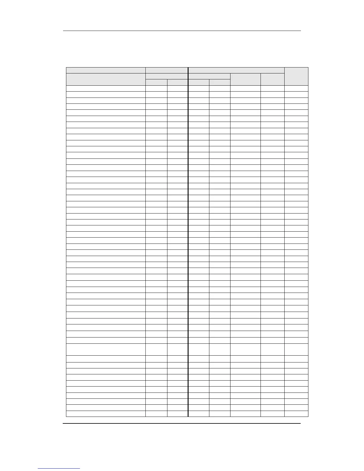
Register table for the fast response normalised actual measurements (in %) (VERSION 1)
The measurements in the registers below are not averaged and therefore the response time is
less than 50 mS.
Active Power Phase L1 (P1)
Active Power Phase L2 (P2)
Active Power Phase L3 (P3)
Reactive Power Phase L1 (Q1)
Reactive Power Phase L2 (Q2)
Reactive Power Phase L3 (Q3)
Reactive Power Total (Qt)
Apparent Power Phase L1 (S1)
Apparent Power Phase L2 (S2)
Apparent Power Phase L3 (S3)
Apparent Power Total (St)
Power Factor Phase 1 (PF1)
Power Factor Phase 2 (PF2)
Power Factor Phase 3 (PF3)
CAP/IND P. F. Phase 1 (PF1)
CAP/IND P. F. Phase 2 (PF2)
CAP/IND P. F. Phase 3 (PF3)
CAP/IND P. F. Total (PFt)
ϕ1 (angle between U1 and I1)
ϕ2 (angle between U2 and I2)
ϕ3 (angle between U3 and I3)
Power Angle Total (atan2(Pt,Qt))
ϕ12 (angle between U1 and U2)
ϕ23 (angle between U2 and U3)
ϕ31 (angle between U3 and U1)