EasyManua.ls Logo

Deif MTR-3 - 6. Measurements; Introduction; Supported measurements list; Available connections

Deif MTR-3
51 pages
To Next Page IconTo Next Page
To Previous Page IconTo Previous Page
Loading...
MTR-3 Installation Instructions
DEIF A/S Page 24 of 51
6. Measurements
Introduction
In the following chapters, the device operation is explained in more details.
Supported measurements
Selection of supported measurements is changed with the connection settings. All supported
measurements can be read via communication (M-Set and Modbus).
Available connections
Different electric connections are described in more details in Electric connection” in chapter 4
“Connection”. Connections are marked as follows:
Connection 1b (1W) − single phase connection
Connection 3b (1W3) − three-phase three-wire connection with balanced load
Connection 4b (1W4) − three-phase four-wire connection with balanced load
Connection 3u (2W3) − three-phase three-wire connection with unbalanced load
Connection 4u (3W4) − three-phase four-wire connection with unbalanced load
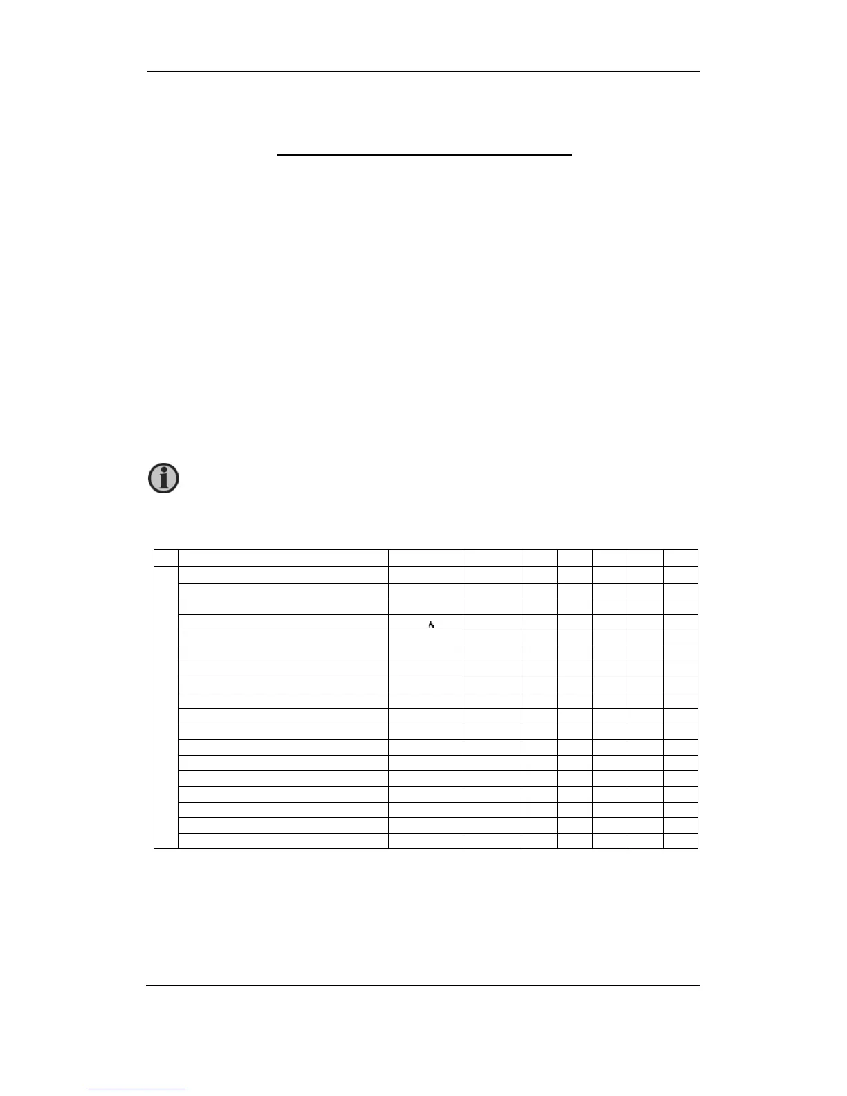
Survey of supported measurements regarding connection mode
Basic measurements
Designat.
Unit
1b
3b
3u
4b
4u
Phase
Voltage U
1
U1
V
×
×
Voltage U
2
U2
V
×
×
×
Voltage U
3
U3
V
×
×
×
Average voltage U
~
U
V
×
×
×
Current I
1
I1
A
Current I
2
I2
A
×
Current I
3
I3
A
×
Current I
n
Inc
A
×
Total current I
t
I
A
Average current I
a
Iavg
A
×
Active power P
1
P1
W
×
×
Active power P
2
P2
W
×
×
×
Active power P
3
P3
W
×
×
×
Total active power P
t
P
W
Reactive power Q
1
Q1
VAr
×
×
Reactive power Q
2
Q2
VAr
×
×
×
Reactive power Q
3
Q3
VAr
×
×
×
Total reactive power Q
t
Q
VAr
supported ○ − calculated × − not supported
Measurement support depends on the connection mode of the instrument type.
Calculated measurements are only informative.