MTR-3 Installation Instructions
DEIF A/S Page 7 of 51
User information
For unknown technical terms, please refer to the below glossary.
Glossary
Term Explanation
Industrial protocol for data transmission
Alternating voltage and current
Angle calculated from total active and apparent power
Angle between fundamental phase voltage and phase current
Total Harmonic Distortion
Measurement of average values in time interval
Connection spot of consumer installation in public network
Defines a number of periods for measuring calculation on the basis of
measured frequency
Defines frequency of refreshing displayed measurements on the basis
of a sample factor
Percentage specifies increase or decrease of a measurement from a
certain limit after exceeding it.
Description of the product
The measuring transducer is intended for measuring, analysing and monitoring single-phase or
three-phase electrical power network. It measures RMS value by means of fast sampling of
voltage and current signals, which makes the instrument suitable for acquisition of transient
events. A built-in micro controller calculates measurements (voltage, current, frequency, energy,
power, power factor, THD phase angles, etc.) from the measured signals.
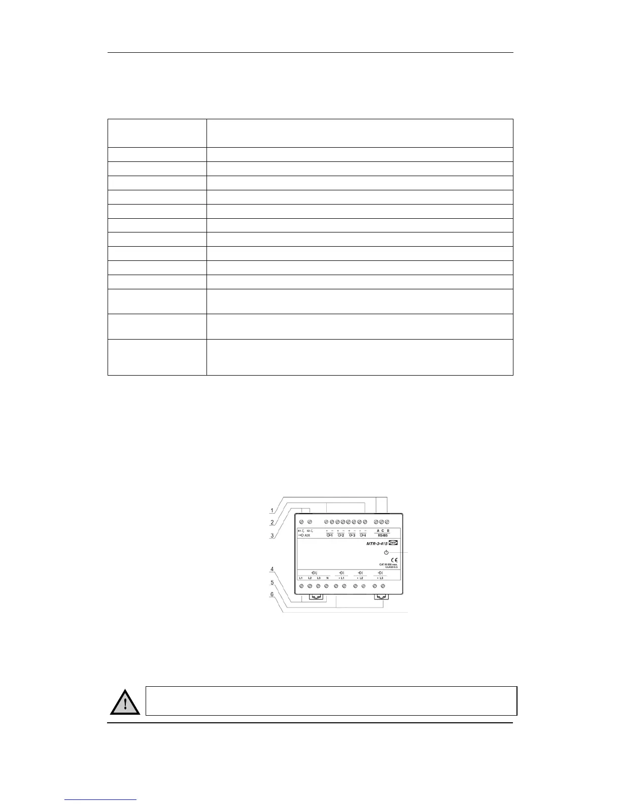
Appearance
The measuring transducer can differ from yours depending on the type and functionality.
1 Communication ports
2 Outputs
3 Auxiliary supply
4 Voltage inputs
5 Current inputs
6 Power ON LED
Communication ports and LED indicators
Serial communication can be connected by using screw-in connector (RS485). A USB can be
connected through a USB-mini type connector at the bottom of the transducer.
LED indicator is intended for POWER ON signalling (red LED).
The USB communication port is NOT galvanically insulated and can be used
ONLY UN-connected to aux. supply and power inputs!