MTR-3 Installation Instructions
DEIF A/S Page 49 of 51
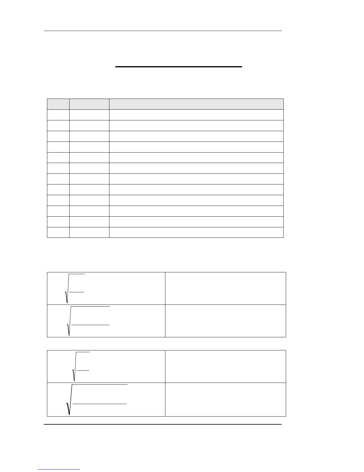
8. Appendix B: Calculations and equations
Calculations
Definitions of symbols
Phase voltage (U
1
, U
2
or U
3
)
Phase-to-phase voltage (U
12
, U
23
or U
31
)
Total number of samples in a period
Sample number (0 ≤ n ≤ N)
Phase-to-phase voltage sample n
Power angle between current and phase voltage f (φ
1
, φ
2
or φ
3
)
N − 128 samples in one period (up to 65 Hz)
N − 128 samples in M
v
periods (above 65 Hz)
Example: 400 Hz → N = 7
u
x
, u
y
− phase voltages (U
f
)
N − a number of samples in a period
Current
N − 128 samples in a period (up to 65 Hz)
N − 128 samples in more periods (above 65
Hz)
( )
N
iii
=
2
n3n2n1
N
1=n
n
I
++
∑
i − n sample of phase current (1, 2 or 3)
N = 128 samples in a period (up to 65 Hz)