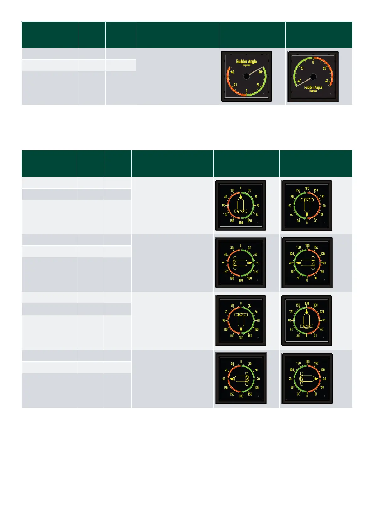
Input type Input 1 Input 2: Pointer position (scale)
FWD design:
EM=6
Pointer CCW1
AFT design:
EM=12
Pointer CCW*
4 to 20 mA - 20 mA
0 to 10 V 10 V -
to 0 to 10 V 10 V -
* Note: Make sure that the pointer rotation matches other indicators/transmitters in the system etc.).
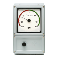
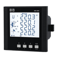
7.3 Standard azimuth indicators
Input type Input 1 Input 2 Pointer position (scale)
FWD design:
EM=12**
Pointer CW*
AFT design: EM=6**
Pointer CW*
4 to 20 mA 4 mA -
0
0 to 10 V
0 V -
to 0 to 10 V V -
4 to 20 mA 8 mA -
0 to 10 V
2.5 V -
to 0 to 10 V V -
4 to 20 mA 12 mA -
180
0 to 10 V
5 V -
to 0 to 10 V 0 V -
4 to 20 mA 16 mA -
0 to 10 V 7.5 V -
to 0 to 10 V 5 V -
* Note: Make sure that the pointer rotation matches other indicators/transmitters in the system etc.).
** Note: EM can be changed 180 degrees (from 6 or 12 by turning the rear side adjustment potentiometer A.
Installation and commissioning guide 4189350024O EN
Page 37 of 39