proxSafe flexx
1.
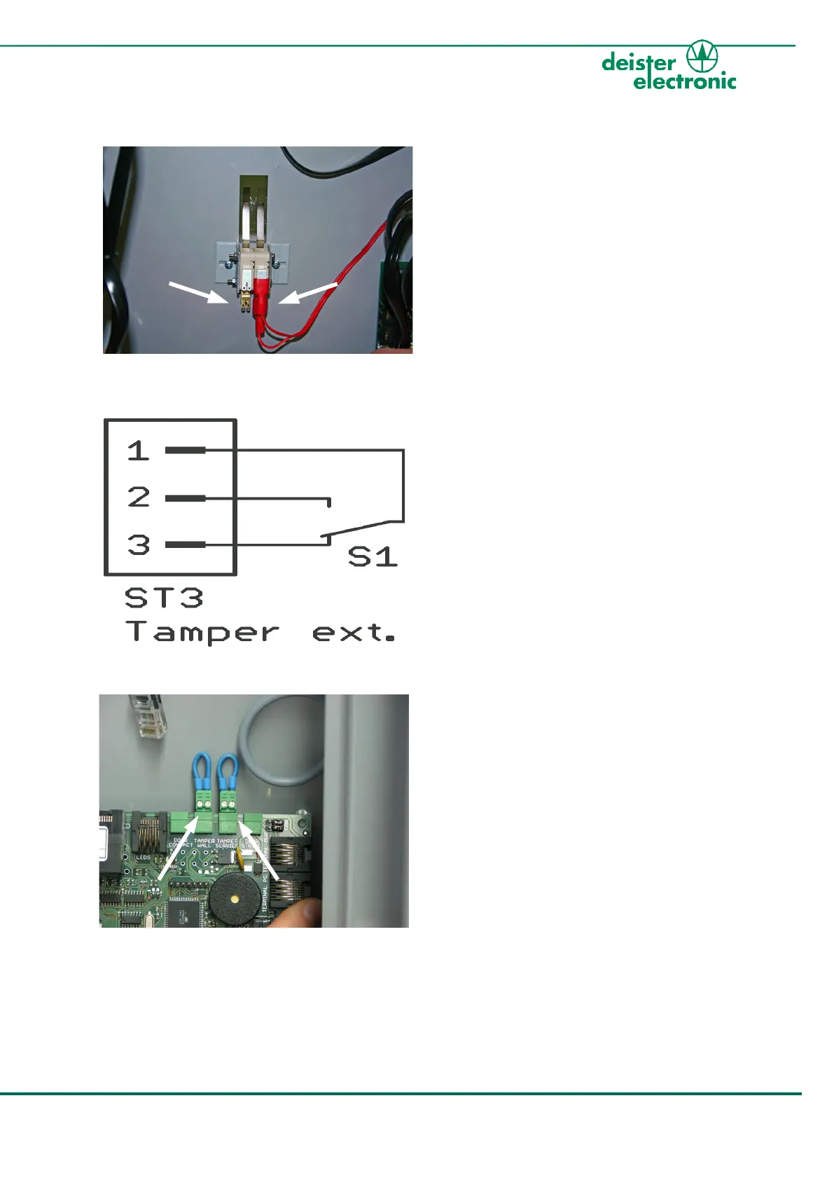
Right: internal tamper switch (a), connected
to input „Tamper Wall“ on backplane PCB
Left: external tamper switch (b) potential-
free; at free disposal for customer
Please remove tape from metal straps
to activate both switches!
2. Diagram of independent tamper switch
(left side: status open --> alarm case!)
3.
Inputs on the flexx backplane PCB for
tamper connection:
Left: „Tamper Wall“ for connection of right
external tamper switch
Right: „Tamper Service“ for connection to
magnetic switch contact on service door
(optional)