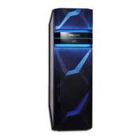
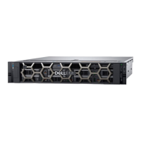
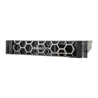
U-Series minimum and maximum configurations..........................................................11
D-Series minimum and maximum configurations......................................................... 13
C-Series minimum and maximum configurations......................................................... 15
Phoenix-16 (Gen1) and Rinjin-16 (Gen2) server chassis front view ............................ 27
Phoenix-12 (Gen1) and Rinjin-12 (Gen2) server chassis front view ............................ 27
Server chassis rear view (all)......................................................................................29
Rear ports on nodes (all)............................................................................................ 29
Cisco 3048 ports (rear).............................................................................................. 35
Cisco 3048 ports (front)............................................................................................ 35
Arista 7010T-48 ports.................................................................................................36
Arista 7048T-48 ports.................................................................................................37
Arista 7050SX-64 ports..............................................................................................38
Arista 7050S-52 ports................................................................................................ 39
Arista 7150S-24 ports.................................................................................................40
Arista 7124SX............................................................................................................. 42
C-Series (Gen1) Integrated disks with node mappings............................................... 46
Pikes Peak chassis......................................................................................................48
Pikes Peak chassis with I/O module and power supplies removed, sleds extended.....49
Enclosure LEDs from the front................................................................................... 49
Sleds letter designations............................................................................................ 50
Drive designations and sled LEDs................................................................................ 51
Disk drive in carrier.....................................................................................................52
Empty drive carrier.....................................................................................................52
I/O module separated from enclosure........................................................................ 53
SAS link LEDs.............................................................................................................53
Power supply separated from I/O module.................................................................. 54
Power supply LEDs.....................................................................................................55
Enclosure fan locations...............................................................................................56
U-Series disk layout for 10-disk configurations (Gen2 only)....................................... 57
U-Series disk layout for 15-disk configurations (Gen1, Gen2 full-rack only)................58
U-Series disk layout for 30-disk configurations (Gen1, Gen2).................................... 59
U-Series disk layout for 45-disk configurations (Gen1, Gen2 full-rack)...................... 60
U-Series disk layout for 60-disk configurations...........................................................61
LCC with LEDs........................................................................................................... 62
LCC Location..............................................................................................................62
Fan control module with LED......................................................................................63
Location of fan modules............................................................................................. 63
ICM LEDs................................................................................................................... 65
DAE power supply...................................................................................................... 66
U-Series single-phase AC power cabling for eight-node configurations .....................73
Cable legend for three-phase delta AC power diagram............................................... 74
Three-phase AC delta power cabling for eight-node configuration............................. 75
Cable legend for three-phase WYE AC power diagram............................................... 76
Three-phase WYE AC power cabling for eight-node configuration............................. 77
D-Series single-phase AC power cabling for eight-node configurations .....................78
Three-phase AC delta power cabling for eight-node configuration.............................80
Three-phase WYE AC power cabling for eight-node configuration............................. 82
C-Series single-phase AC power cabling for eight-node configurations: Top .............83
C-Series single-phase AC power cabling for eight-node configurations: Bottom ....... 84
C-Series 3-phase AC power cabling for eight-node configurations: Top ....................85
C-Series 3-phase AC power cabling for eight-node configurations: Bottom .............. 86
U-Series (Gen2) SAS cabling for eight-node configurations....................................... 91
U-Series (Gen2) SAS cabling..................................................................................... 92
1
2
3
4
5
6
7
8
9
10
11
12
13
14
15
16
17
18
19
20
21
22
23
24
25
26
27
28
29
30
31
32
33
34
35
36
37
38
39
40
41
42
43
44
45
46
47
48
49
50
51
52
53
FIGURES
D- and U-Series Hardware Guide 5

 Loading...


