Table 5 Embedded module LEDs (continued)
LED Location State Description
Off No fault has occurred, normal
operation.
Storage processor assembly
power
Green Storage processor assembly
is on (main power).
Green blinking Storage processor assembly
is initializing a serial over LAN
session (Standby Mode).
Off Storage processor assembly
is off.
Unsafe to remove White Do not remove the embedded
module. Improper removal
could cause data loss.
Off Safe to remove the embedded
module when the embedded
module has been properly
prepared.
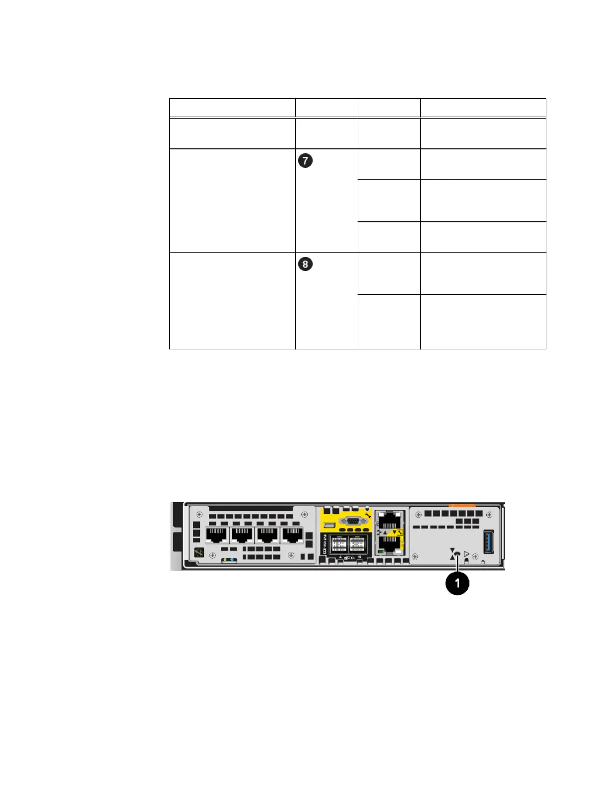
Nonmaskable interrupt (NMI) button
The nonmaskable interrupt (NMI) button is a recessed button located on the
embedded module, which is used to reset the system password or force a system
reboot.
Use a bent paper clip or pen to press the recessed button. Press the button for
approximately 2 seconds to reset the password. The SP assembly fault LED blinks blue
when the password has been successfully reset.
Press the button for 10 or more seconds to force a system reboot.
Figure 8
Location of the NMI button on the embedded module
DPE I/O module types
I/O module installation priority
There are two I/O module slots per SP assembly: slot 0 and slot 1. Slot 0 has a 16 lane
PCIe channel, and slot 1 has an 8 lane PCIe channel.
Populate new I/O modules in the following order to take advantage of the increased
speed on slot 0. If two I/O modules are ordered, use the same installation priority for
both I/O modules.
DPE component descriptions
14 Unity 480/F, Unity 680/F, Unity 880/F Hardware Information Guide
 Loading...

