Table 3. Expansion module packing list - 4G(continued)
Item Quantity Notes
Antenna 2 -
4G label 1 -
4G heat sink 1 -
Thermal pad 1 -
Table 4. Tools needed
Tool Notes
Phillips head screwdriver Small size
Needle-nose pliers —
Nut drivers 4.5 mm, 5 mm, 5.5 mm, 8 mm
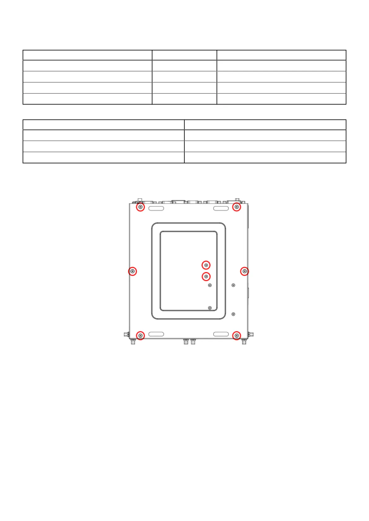
Steps
1. Remove the eight screws from the bottom panel of the EGW-5200, as shown in the following figure, and remove the bottom
panel.
Figure 12. Bottom panel screw locations
2. Remove the screws and nuts from the inside of the bottom panel, as shown in the following figure. Hold the nuts from inside
the panel while unscrewing. Discard these four sets of screws and nuts.
12
Installation procedure for 4G expansion module